
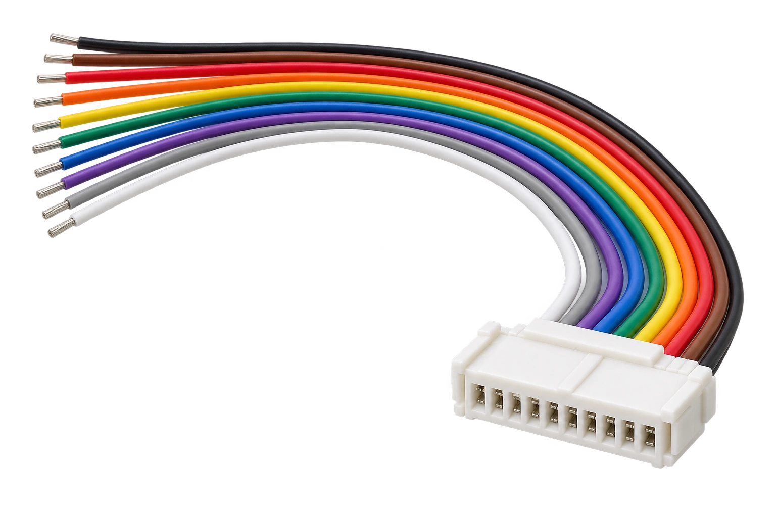
Generated visualisation of discrete-wire construction. Final connector, wire and end-finish details follow the order drawing.
Multiwire Harness Constructions
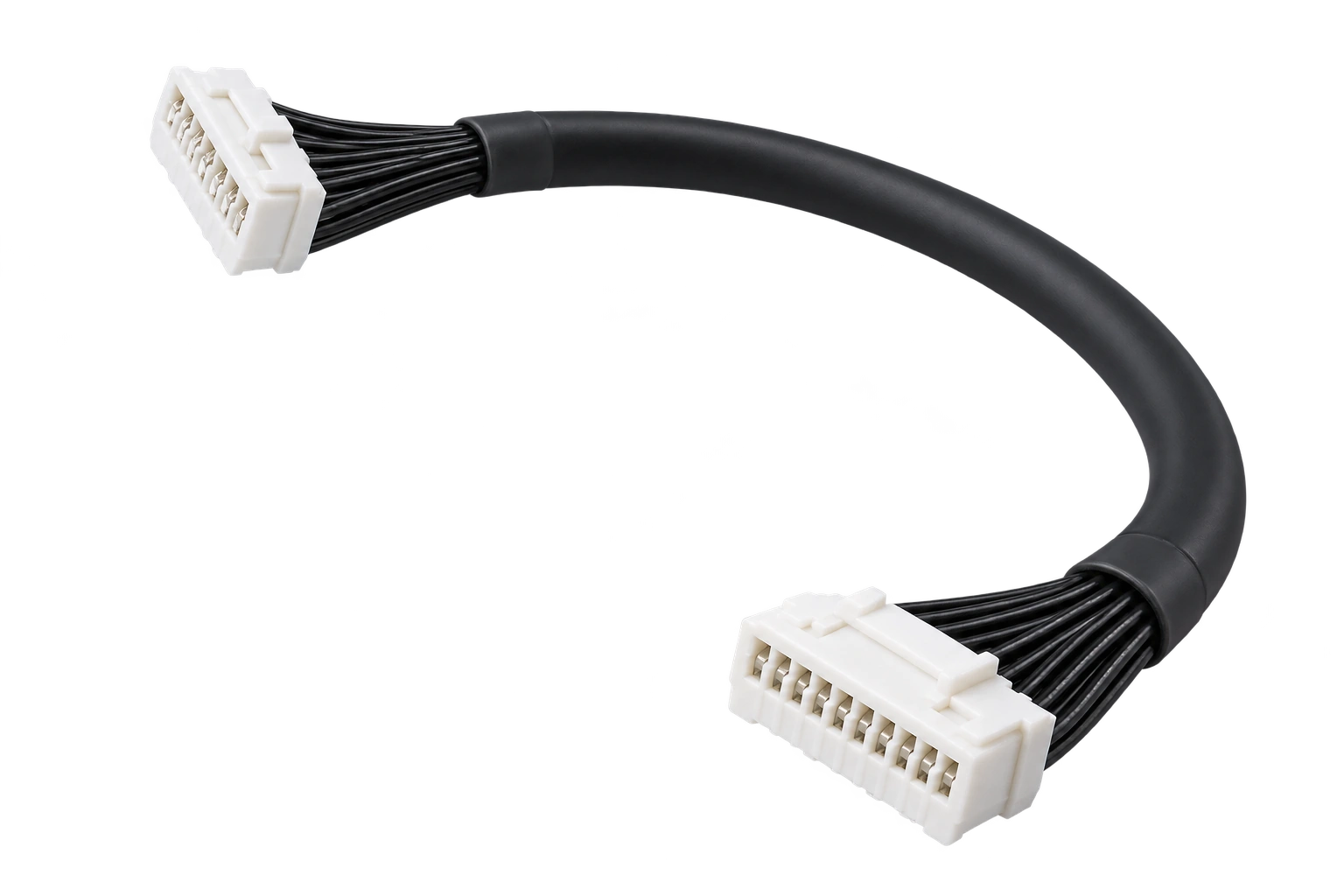
Compare separate leads, flat coloured wire groups and covered harnesses. Generated visuals illustrate JTY catalogue constructions; connector geometry and end finishes follow the order drawing.
View Original Catalogue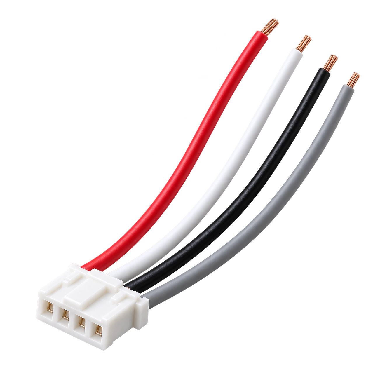
Discrete-Wire Connector Leads
Separate leads suit layouts where connection points are spread apart and individual wires need to follow different paths.
Request Discrete-Wire Connector Leads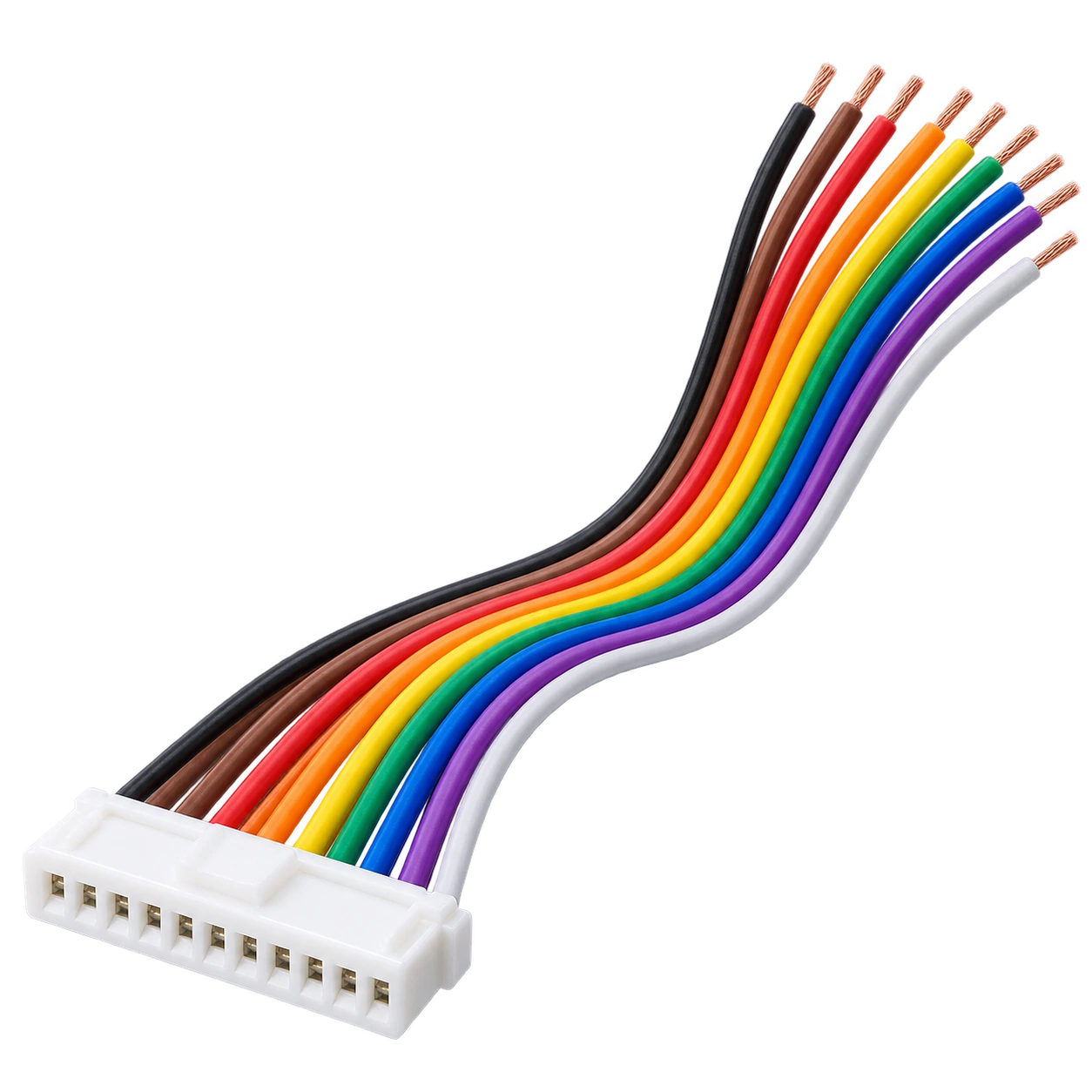
Flat Multicolour Wire Leads
Parallel coloured leads suit a flat side-by-side run where each colour can be matched to its intended connection point.
Request Flat Multicolour Wire Leads
Covered Multiwire Connector Harnesses
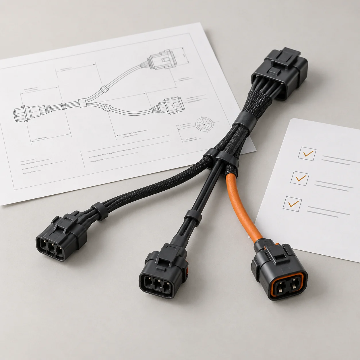
Covered wire groups suit a shared route where the covering ends leave enough exposed lead length to reach the separate connection points.
Request a Covered Multiwire HarnessCompare the Supplied Connector Build
The ordered build covers the assembled cable-side connector, its fitted wires and their opposite ends.
Housing, Contacts and Mating Parts
The housing alone is one component; the finished harness includes fitted contacts and wires. The supply list distinguishes the assembled harness from any mating counterpart included in the order.
Populated and Unused Positions
Connectors with the same number of cavities can have different populated positions and wiring. Occupied positions determine the fitted wire and contact quantities. The connector view and latch orientation identify which cavities the position map refers to.
Each Wire and Its Opposite End
Each wire ID links a housing position to the finish or connector at the opposite end. Separate IDs distinguish wires that share a colour.
Populated-Position Schedule
- Position
- J1-A
- Wire ID
- W01
- Wire colour
- Black
- Opposite end
- E01, cut end
Illustrative position schedule. Connector, wire, contact and end references are examples. The diagram does not describe a particular JTY assembly.
Define the Wire Group That Reaches Your Equipment
The equipment layout determines the reach and routing space needed for each lead.
Individual Wire Reach
Each lead must reach its connection point along the intended route. The drawing's datum, measurement path and wire condition establish how its finished length is measured.
Covering and Exposed Leads
The covering boundaries set where the wires emerge as exposed leads. The exposed length at each end affects how far each wire can follow its route to the connection point.
Wire Identification
The JTY catalogue shows identification sleeves on a separate multiwire sample. When sleeves are included in the order, their text and positions link each lead to its wire ID in the connection schedule.

Contact Termination & Harness Assembly
JTY supplies the terminated wires, loaded housings and wire-group finish specified for the harness build.
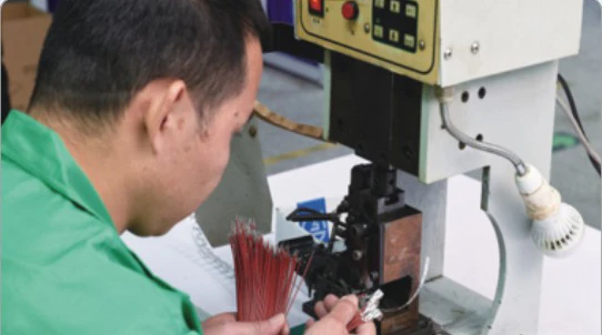
Contact Termination
JTY processes and crimps the ordered wire and contact combination. The contact must suit both the conductor and insulation of the selected wire.

Housing Loading
JTY inserts the contacts into the ordered housing positions. The position schedule controls wire placement; the selected housing and contact determine the seating requirements.
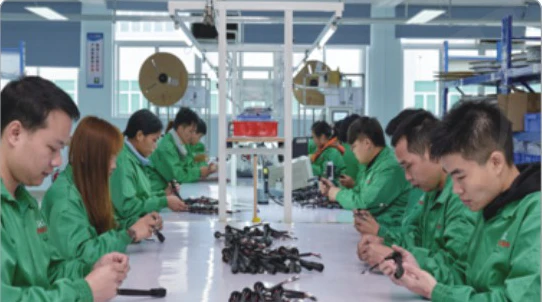
Wire Grouping & Finish
The finished assembly follows the selected loose, parallel or covered construction. Covering boundaries and any wire identifiers follow the ordered drawing revision.
Define the Checks for the Ordered Harness
The inspection plan connects each selected check to its acceptance criteria, sample quantity and required record. The plan forms part of the order agreement.
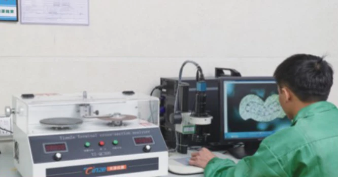
Wire and Contact Termination
Cross-section inspection examines the crimp structure and section geometry of the selected wire and contact against agreed criteria.
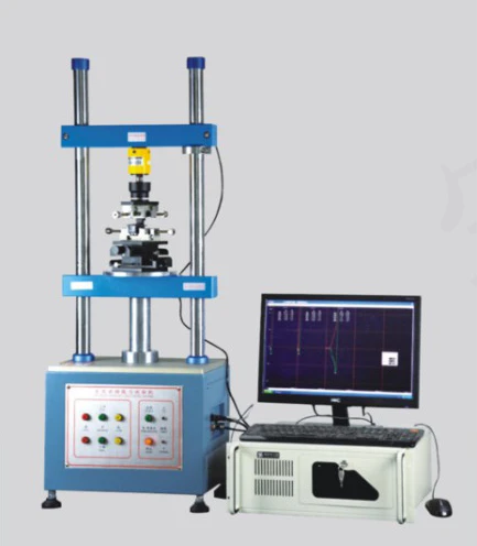
Connector Assembly and Mating
Assembly review compares occupied positions and wire IDs with the position schedule, and contact seating with the selected housing and contact requirements. Insertion and withdrawal testing addresses the selected mating pair under agreed conditions and force limits. Electrical continuity and point-to-point mapping are separate checks when included in the agreed plan.
Dimensions and Wire-Group Finish
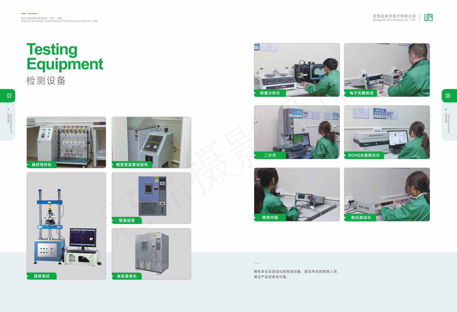
Full-assembly length measurement depends on the agreed datum, measurement path, wire condition, method and limits. Covering boundaries and identifiers can be checked against the drawing. JTY has dimensional equipment for local component geometry.
Inspection Request
Wire/contact termination
- Order reference
- Wire and contact references
- Requirement to include
- Crimp criteria, sample quantity and record
Loaded connector
- Order reference
- Position schedule and housing/contact assembly requirements
- Requirement to include
- Occupancy, wire ID and seating review
Connector mating
- Order reference
- Mating-part references
- Requirement to include
- Test conditions, force limits and sample quantity
Wire-group dimensions
- Order reference
- Assembly drawing and revision
- Requirement to include
- Datum, path, wire condition, method, limits and record
Where records are included, each result should be linked to the relevant wire and contact combination, mating pair or drawing revision.
Include Inspection Requirements in the RFQMultiwire Harness RFQ
Bring the component supply list, populated-position schedule and wire-group dimensions together in the harness enquiry. The worksheet includes quantity and inspection requirements alongside the assembly definition.
Contact Us
Tell JTY about your connector, wire harness or cable assembly project. Share the drawings, specifications or sample details you have for an initial review.
 Your Project