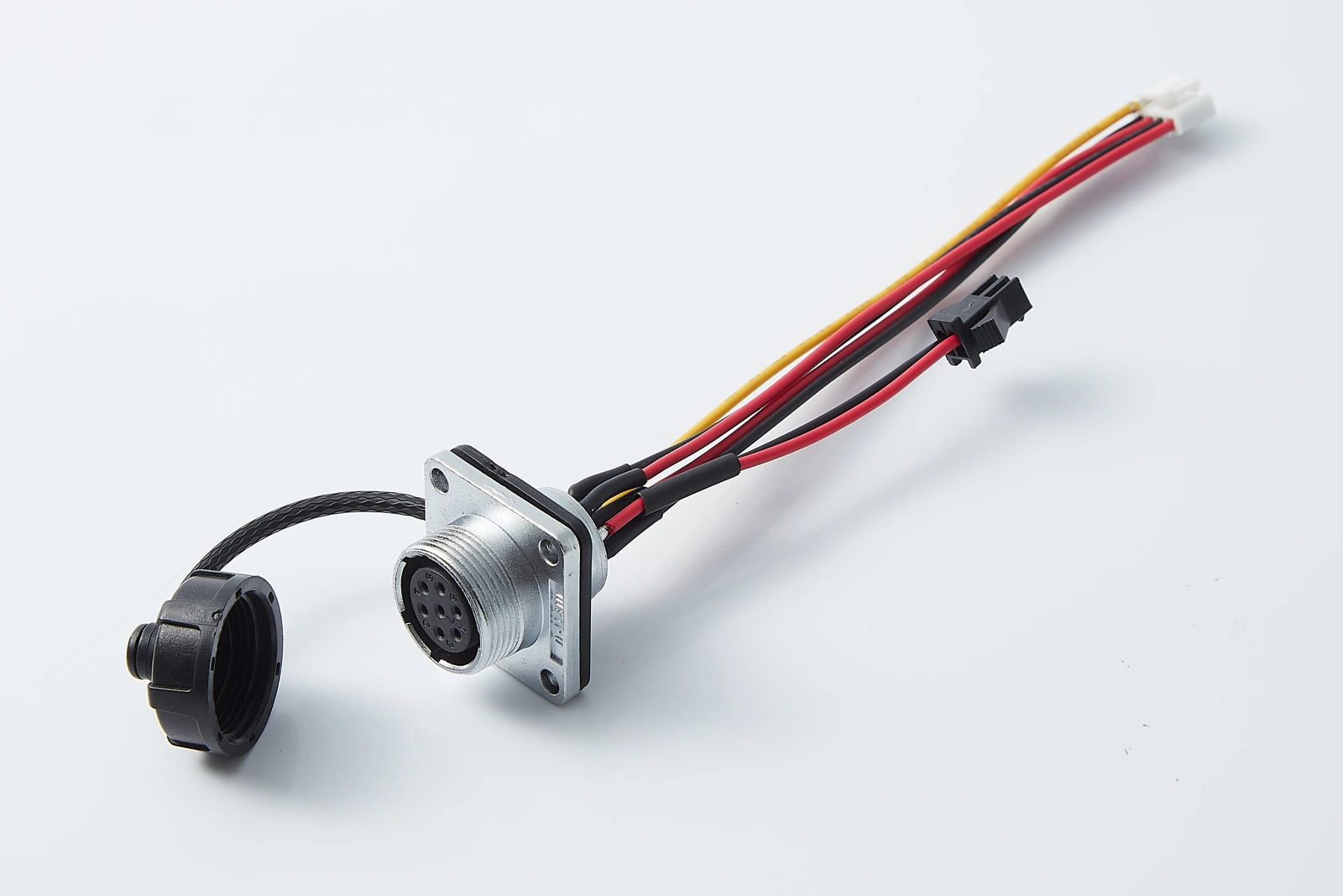
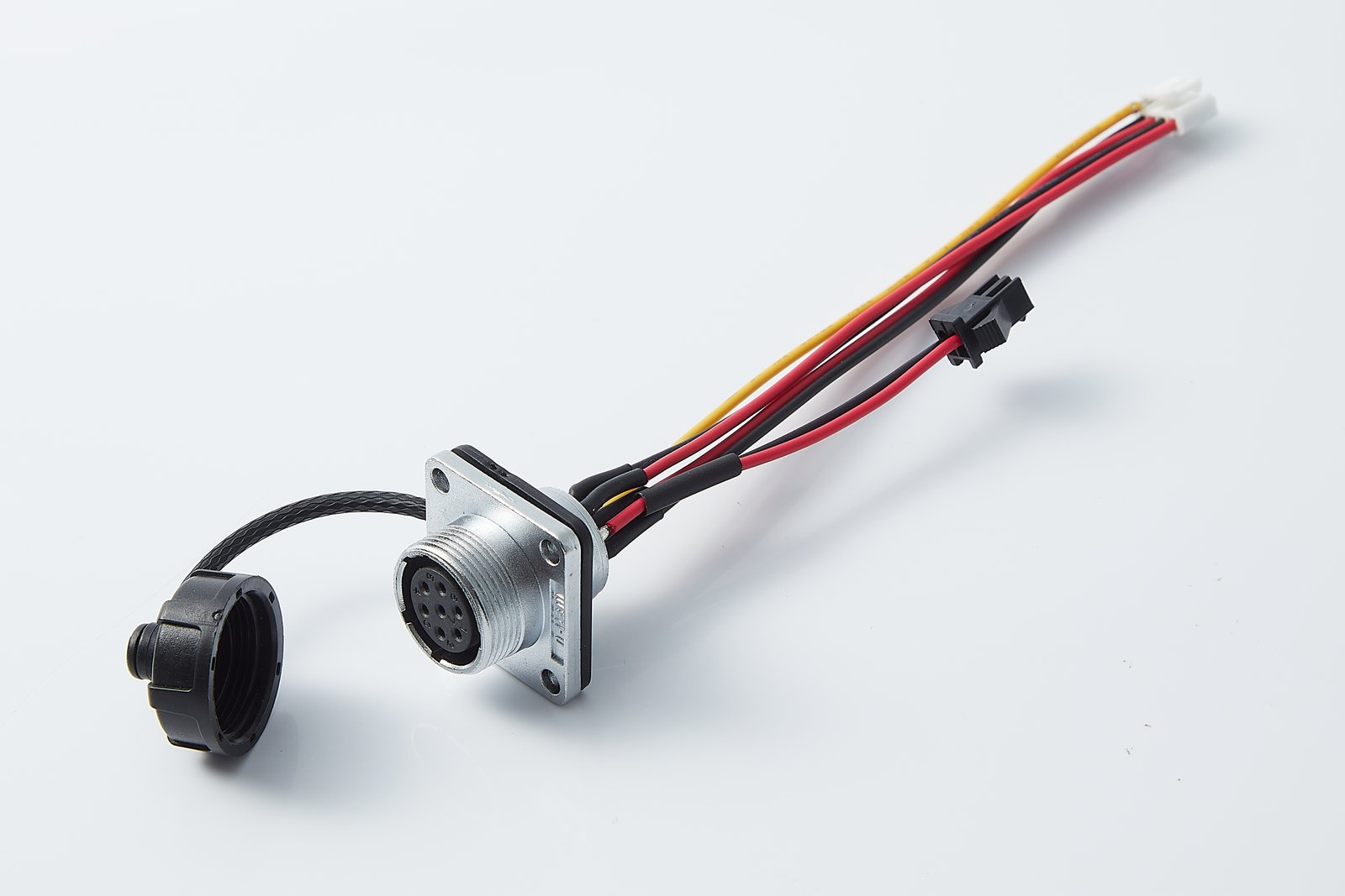
JTY panel assembly with connector-ended leads.
Panel-Mount Assembly Constructions
Compare the attached wiring and equipment-side ends on these two JTY samples. Open each construction for its end details and supply scope.
Connector-Ended Panel Assembly
Choose fitted lead-end housings when the equipment build calls for a plug-in connection at those leads.
View Connector-Ended Construction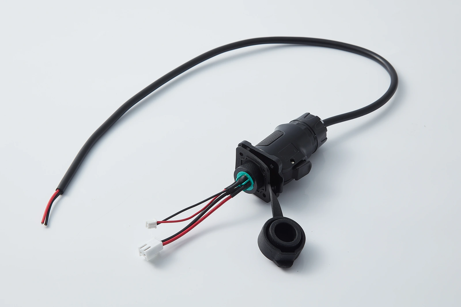
Cable-and-Tail Panel Assembly
This construction combines fitted lead-end housings with open wire tails that the equipment builder can terminate during assembly.
View Cable-and-Tail ConstructionPhotographs show assembly constructions. The customer drawing or assembly BOM specifies component references, circuit connections and dimensions.
Compare the Supplied Assembly Ends
Connector-Ended Panel Assembly
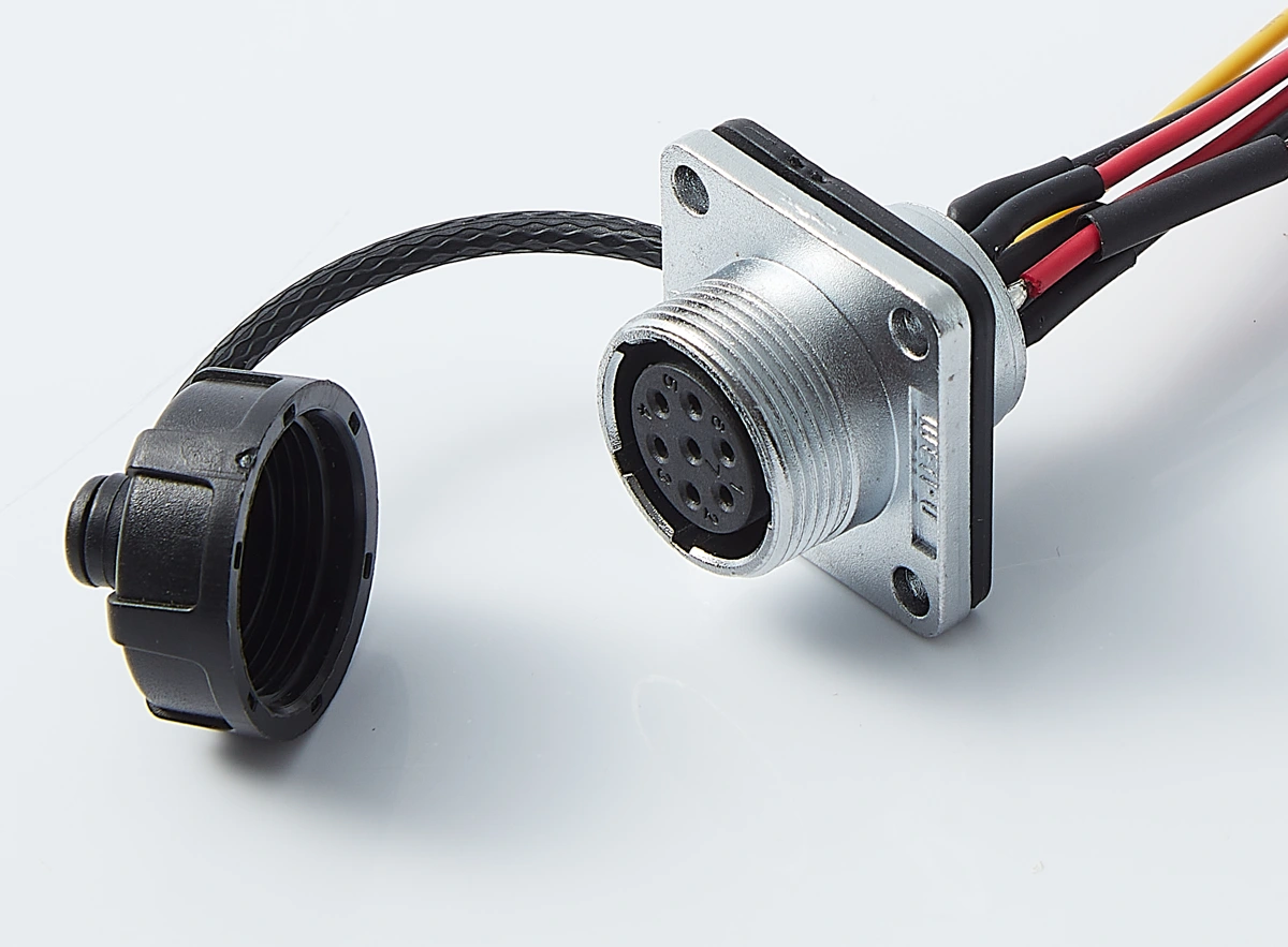
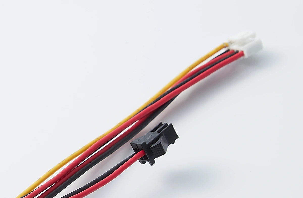
The silver flange sample has attached leads ending in small connector housings.
- Panel-side interface
- The sample’s circular interface sits within the flange. List the panel mating connector by part number, quantity and supplying party.
- Equipment-side ends
- The fitted lead-end housings are part of the wired assembly shown. Use the connection schedule to identify where each lead ends and which connector position it uses, where applicable.
Cable-and-Tail Panel Assembly
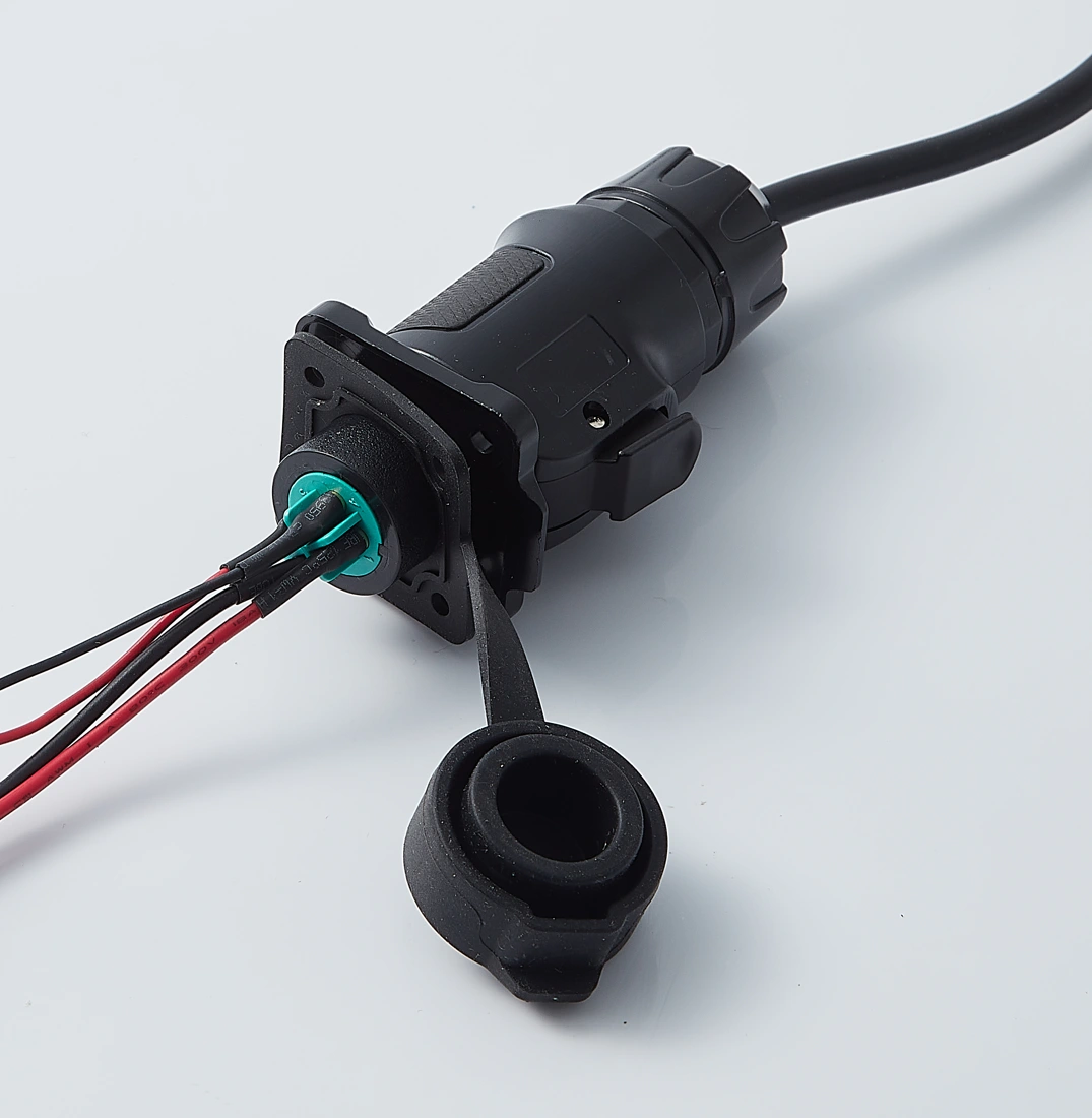
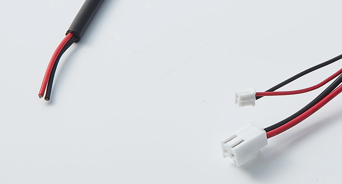
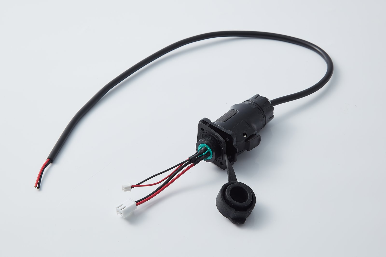
The black assembly combines a sheathed cable with open red and black tails and smaller connector-ended leads.
- Open Tails and Connector Ends
- The order specifies the preparation for each open tail and identifies the connector ends that arrive fitted.
- Connection Schedule
- Use the customer connection schedule to identify each endpoint and circuit connection.
Wired Assembly and Separately Listed Parts
| Order item | Details for the Assembly Order |
|---|---|
| Panel component and wiring | Component reference, attached cable or leads, equipment-side end finish and assembly quantity. |
| External mating part | Mating-part reference, required quantity and supplying party. |
| Cap, fixings and sealing parts | Individual part references, quantities and supplying party. The cap shown on a sample is not a default inclusion for every order. |
Panel Connections in Rack and Control Equipment
The wiring must reach each connection point along the installed route. The equipment build sequence determines when each end can be connected.

Rack-Mounted Equipment Panels
Trace the route from the fixed panel port to each connection point in the rack-mounted equipment. Allow for any brackets, boards or other parts the wiring must pass around.
Mark the endpoints and length measurement points on the assembly drawing.
View Connector-Ended ConstructionControl Enclosures
Check which ends can be connected on a wiring bench and which need access after the panel is installed.
Use that sequence to specify which ends arrive fitted and which remain open for final termination.
View Cable-and-Tail ConstructionSelect the connector reference and required electrical and environmental ratings for your equipment. The sample photographs do not establish device compatibility or an installed IP rating.
Panel Fit Requirements for the Wired Assembly
Use the selected component drawing and the customer panel layout for the fit check. Check the actual panel thickness against the component’s permitted range, where specified.
Body Opening and Fixing Holes
The silver sample shows a mating face and flange fixing holes. Use the component drawing to lay out the body opening and locate the fixing holes.
Installation Side and Tool Access
Mark the connector orientation, insertion side and fastening side on the panel layout. Check tool access with nearby parts in place.
Mating Interface
The electrical mating-part reference stays with the installation drawing. Matching fixing patterns do not establish connector interchangeability.
Installation Drawing Reference
ATTEND's M-series guide identifies the insertion side and nut-fastening side separately.
ATTEND drawing reference. Its construction and dimensions do not describe the JTY samples.
View ATTEND Installation DrawingDelivered Ends and Rear-Space Requirements
The delivered end form affects the route available for installing the wired assembly.
Check the Largest Delivered End
Where the installation route passes through a restricted opening, the fitted housings belong in the passage check. The order drawing records the required delivered end state before manufacture.
Body and Cable-Exit Envelope
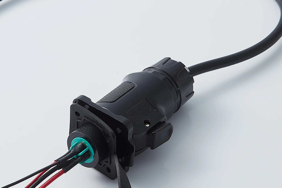
The black sample shows a connector body and a sheathed cable exit. Mark the available depth, cable route and any required support points on the equipment layout. Check the component clearance and cable bend radius against the selected part documents.
Mating Connector and Cap Access
The equipment layout also defines the space needed to mate the external connector or operate the specified cap. This access area is separate from the rear cable route.
Panel-Mount Prototype and Production Builds
JTY manufactures wired assemblies from customer drawings or physical samples.
Terminal Processing
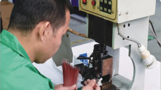
JTY has terminal-processing equipment. Specify the selected contact and wire together, since both affect the termination method.

Cable and Housing Assembly
For the quote, specify lead lengths, fitted housings and open-tail preparation in the assembly drawing and referenced connection schedule.
Prototype Assemblies for Equipment Fit Checks
Prototype and production supply are available. Use a wired prototype to check panel fit, rear space and the specified connections in your equipment. Record agreed changes against the drawing revision or sample reference for the next order.
Assembly Acceptance and Inspection Requests
Use the installation requirement and assembly BOM as acceptance references. Keep the customer's equipment fit check separate from the requested JTY inspection scope.
Customer Equipment Fit Check
The customer equipment trial uses the panel layout as its fit reference. Requested observations and any installation deviations belong in the acceptance record.
Assembly and Accessory Identity
The BOM check records the supplied component references, delivered end states and accessory quantities against the order.
Specified Dimensions
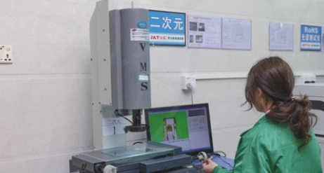
Dimensional inspection requests use the order drawing to identify the measurements required. The schedule below links each requested dimension to its datum, limit, quantity and record.
Connector Insertion and Withdrawal
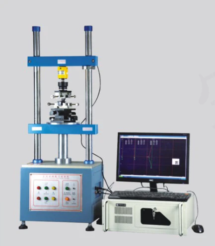
JTY has connector insertion and withdrawal test equipment. Specify both mating part numbers, the measurement directions, test conditions and force limits for the pair.
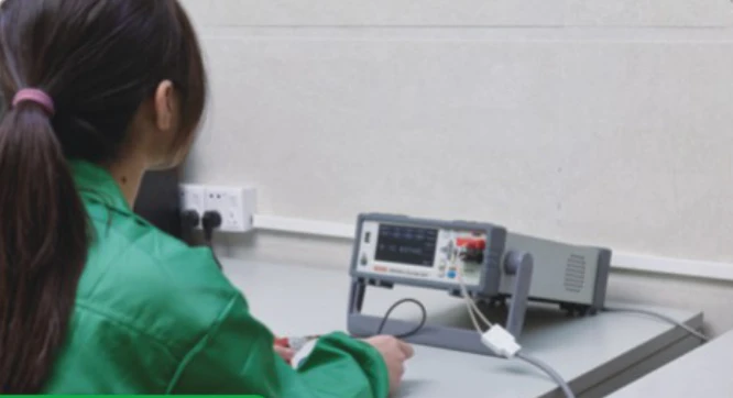
Resistance Measurement
JTY has precision resistance-measurement equipment. Identify the endpoints and specify the measurement method, test conditions and agreed resistance limit.
Sealing Conditions in the Installation Requirement
The sealing requirement identifies the connector's mated or capped state and the connector-to-panel interface. The sample photographs do not establish an installed-assembly IP rating.
Acceptance Schedule
| Check | Required reference and criterion | Requested record |
|---|---|---|
| Customer equipment trial | Customer panel layout and assembly reference | Fit observations and installation deviations |
| Assembly identity | Order BOM, delivered ends, accessory references and quantities | Reference and quantity comparison |
| Dimensional checks | Dimension reference, datum, limits and inspection quantity | Requested measurement values with drawing references |
| Connector insertion and withdrawal | Both mating references, measurement direction, conditions, force limits and quantity | Requested insertion and withdrawal force values for the named pair |
| Resistance measurement | Connection endpoints, measurement method and conditions, resistance limit and quantity | Requested resistance values for the identified endpoints |
Inspection resources do not establish test results or default whole-assembly coverage. The required checks and records form part of the inspection enquiry.
Include Acceptance RequirementsPanel Installation & Assembly RFQ
Send your existing drawing, BOM or sample details with the required quantities. The sheets below collect missing installation and assembly-order details.
Panel Installation Sheet
Record installation side, opening references, panel thickness, available space and assembly sequence.
Fill in browser / print to PDF
Download Installation SheetAssembly Supply-Scope Worksheet
Record component references, supplied ends, accessory responsibility, quantities and requested checks.
CSV worksheet
Download Supply-Scope SheetThe worksheets are optional.
Send Drawing or Sample DetailsContact Us
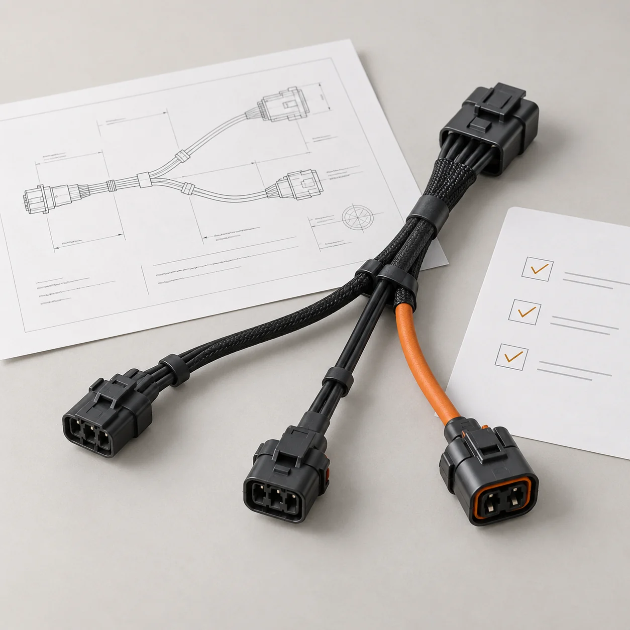
Tell JTY about your connector, wire harness or cable assembly project. Share the drawings, specifications or sample details you have for an initial review.
 Your Project