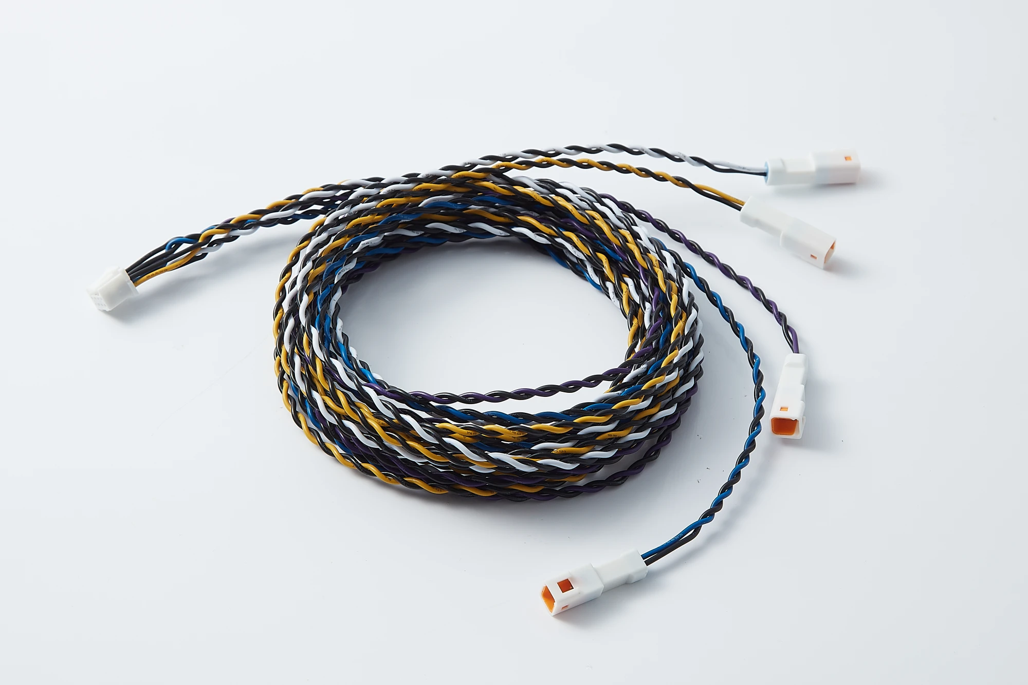
JTY twisted-wire branch sample.
Branched Assembly Constructions
Compare exposed twisted-wire groups with separately covered branches. Open a construction to review its ends and drawing requirements.
Twisted-Wire Branch Assembly
The pictured twisted-wire construction suits connector-to-connector branches that reach separate equipment connection points.
View Twisted-Wire Construction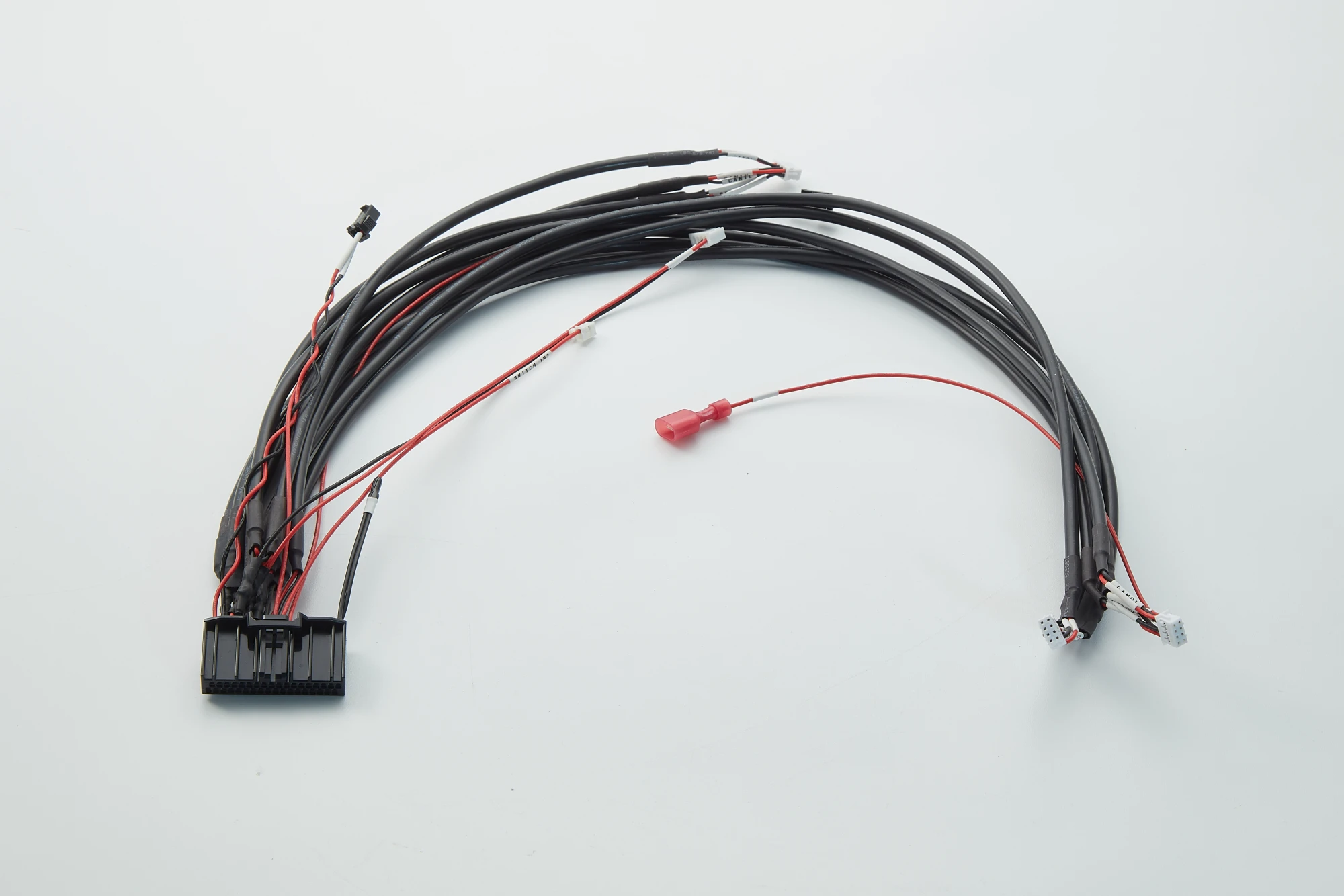
Covered Branch Cable Assembly
The pictured covered construction suits branches with different end connections, with exposed tails to position the connectors and insulated terminal at their connection points.
View Covered ConstructionThese photographs show JTY construction samples. Connector references, circuit allocation and branch dimensions follow the ordered assembly drawing.
Review the Assembly Ends
The main connector and branch ends form the supplied harness. Equipment-side mating parts are separate items when included in the order.
Twisted-Wire Branch Assembly
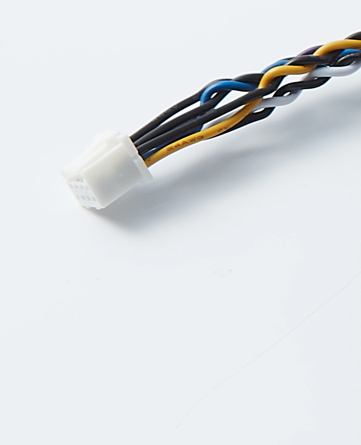
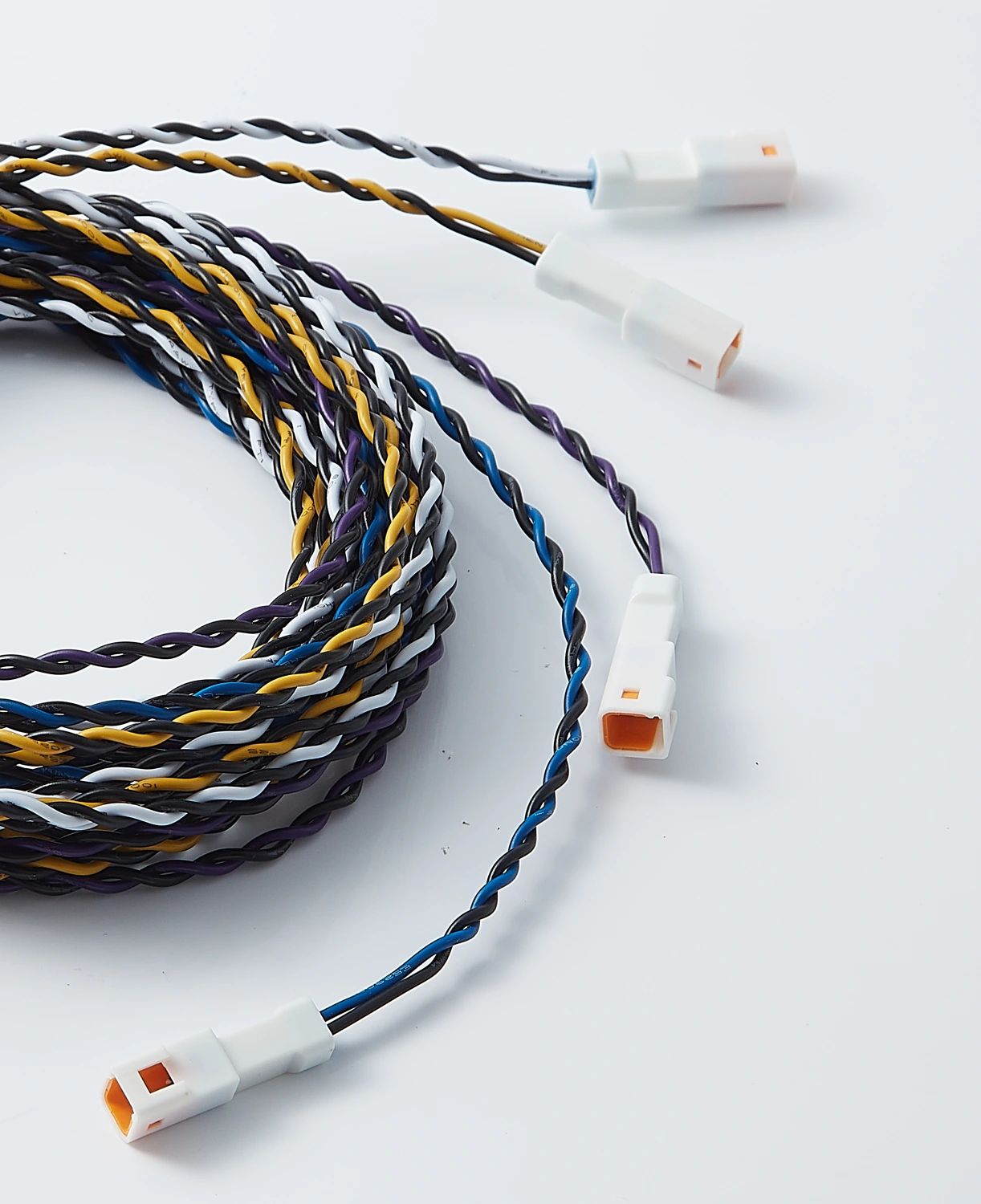
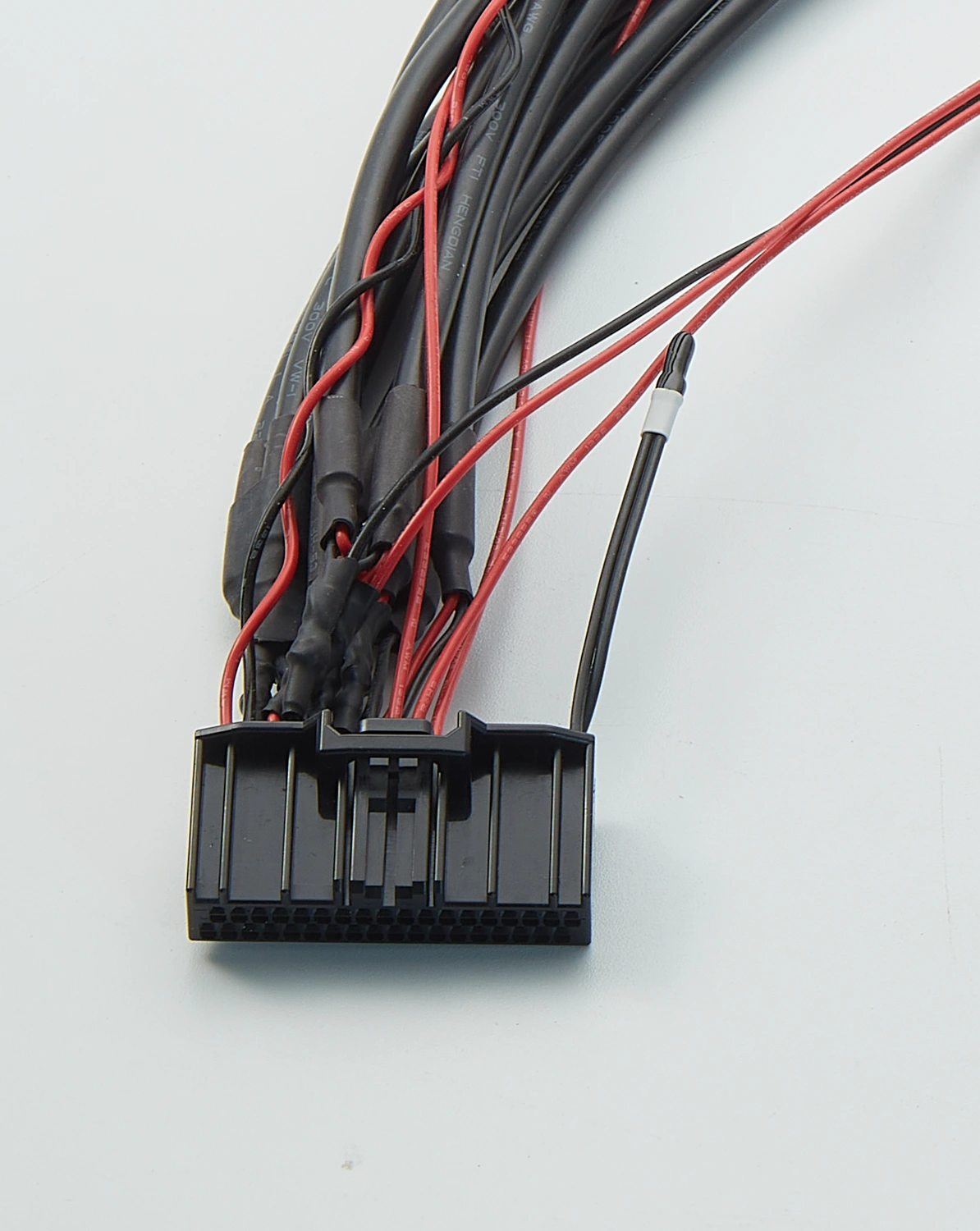
Exposed twisted-wire groups run from the main housing to separate small connector ends.
- Main-end supply
- The pictured main end includes the housing, fitted contacts and wires. With housing-only supply, contact fitting and wire termination remain separate assembly work.
- Branch-end allocation
- Four small connector ends are visible on this sample. The order assigns each branch to its equipment connection; similar-looking ends do not establish the same cavity assignment or wiring.
Covered Branch Cable Assembly
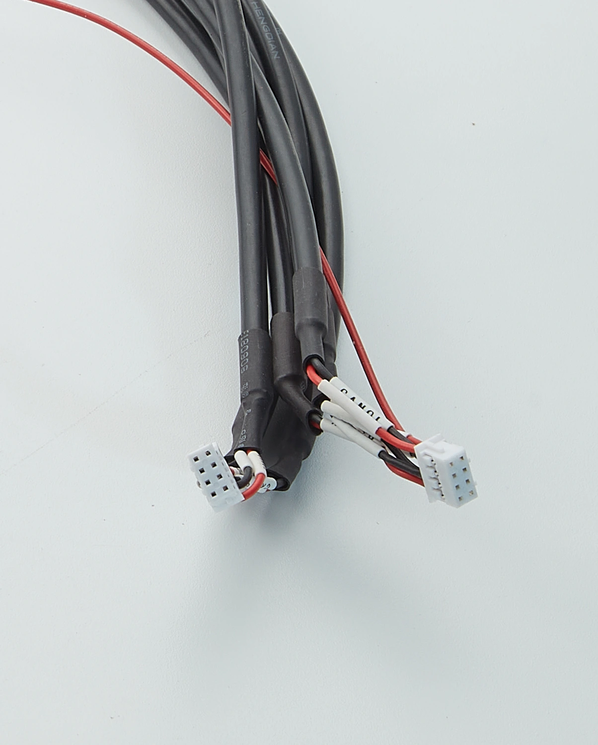
Separate black coverings leave exposed end wires for the small connector and insulated terminations.
- Covered branch ends
- The pictured coverings stop before the fitted connectors and insulated termination. The exposed wires at these branch ends are already terminated.
- End-state schedule
- The sample combines connector and insulated termination ends for different connection needs. Matching cover colour does not make those ends interchangeable or establish the same end state.
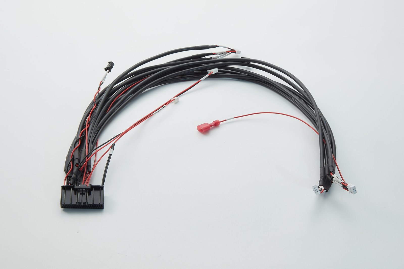
Detail crops from the same two JTY samples shown above. Connector references, cavity assignments and electrical ratings are not identified by these photographs.
Set the Breakout Positions and Branch Reach
JTY builds the branch layout into the supplied assembly. The drawing locates the main run, each breakout and each branch end.
Branch Layout Requirements
Breakout Position and Free Branch Length
The same J0-to-B1 end-to-end dimension can have different main-run and free-branch lengths. Moving the breakout changes the free branch available to reach the equipment port.
Separate Dimensions for Each Branch
Each branch has its own endpoint and length reference. The layout states the connector datum, measurement path and cable condition. Multiple breakouts along a main run need separate position dimensions. The order and inspection use the same drawing revision and measurement references.
Covering Boundaries
The physical breakout and covering end are separate features on the drawing. The covering end and connector entry define the exposed wire length available for the final route to the connection.
Define Branch Destinations and Circuit Allocation
Each branch ID links a harness end to its equipment destination. The connection schedule separately shows which endpoints belong to each electrical network.
Customer requirement examples. These labels are not verified pin assignments for the JTY samples. Shared networks require a wiring diagram with junction and conductor requirements for technical evaluation.
Independent Circuits
Separate main-end positions connect to separate branch endpoints in this example.
| Network | Required endpoints |
|---|---|
| NET1 | J0.A / B1.A |
| NET2 | J0.B / B2.A |
Shared-Circuit Requirement
The wiring requirement places several branch endpoints on the same network.
| Network | Required endpoints |
|---|---|
| NETS | J0.C / B1.B / B2.B |
Physical branches do not establish parallel wiring. The network requirement defines which endpoints are electrically connected; the branch layout defines where they reach. Similar-looking assemblies or the same branch count do not establish the same wiring.
Branch Destination Schedule
| Branch | Equipment destination | Connection reference |
|---|---|---|
| B1 | Device A port | Drawing / network reference |
| B2 | Device B port | Drawing / network reference |
Example destinations only.
Branch Assembly, End Processing and Sample Builds
JTY manufactures branched harnesses from drawings or samples. The ordered build includes the wire groups, specified end processing and branch covering.
Terminal Processing and Housing Assembly
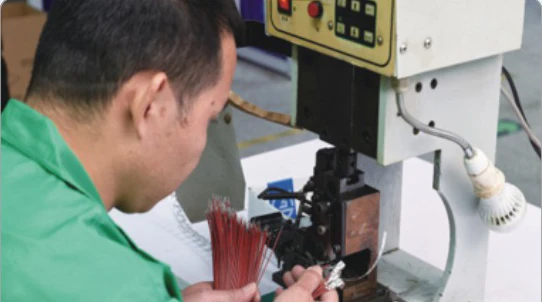
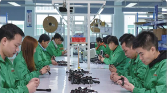
JTY crimps the selected terminals onto the wires and loads the contacts into the specified housings.
Branch Grouping and Covering
JTY groups the wires into branches and applies the specified covering as part of harness assembly.
Prototype to Production
Prototype and production supply are available. The prototype can be fitted in the equipment to check the main connector and branch reach. Subsequent orders can reference the accepted drawing revision or sample identification.
Choose the Supplied End State
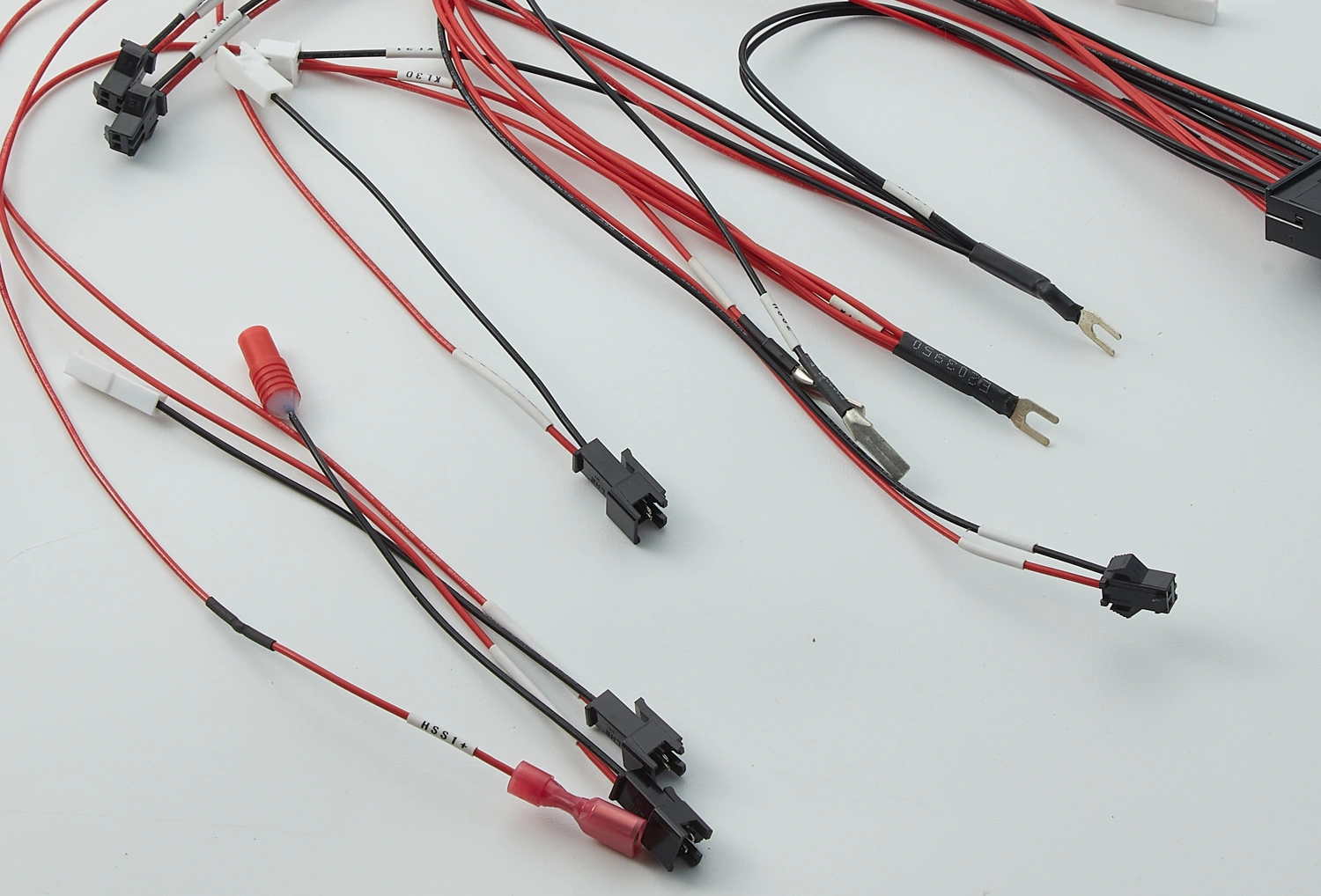
Other JTY samples show mixed terminations and prepared open tails. The end schedule distinguishes completed terminations from prepared leads awaiting final equipment-side termination.
Mixed-End Branches
The pictured sample combines small connector ends, fork-shaped metal ends and insulated terminations. These fitted ends arrive as part of the supplied assembly.
View Original Photo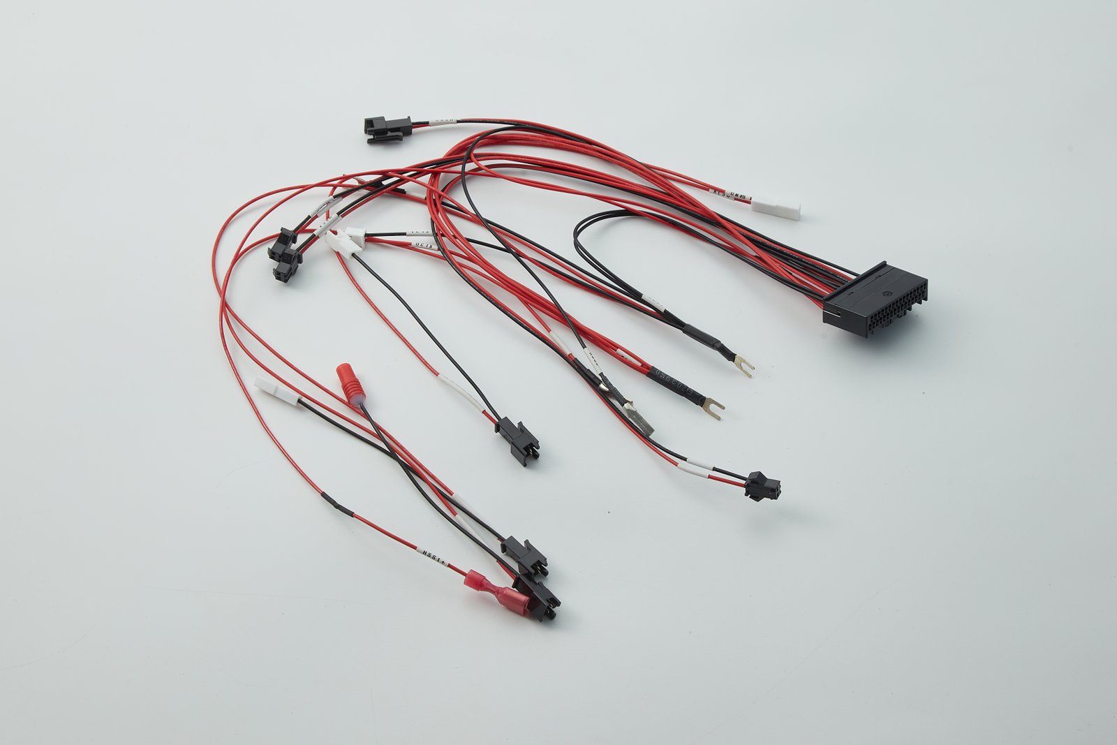

Open-End Branches
Prepared wire tails leave the final equipment-side termination to the customer. The pictured sample has covered main wiring with separate open wire ends.
View Original Photo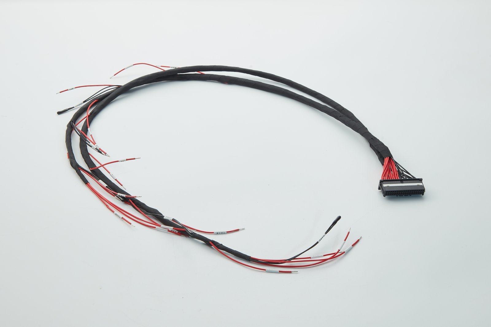
Match Inspection to the Branch Drawing
The inspection plan connects the selected checks with their acceptance criteria, sample quantities and records. The branch drawing and connection schedule give each check its reference.
Branch Geometry and Identification
The branch layout provides the reference for breakout locations, branch reach, covering ends and destination identifiers. For branch lengths, the drawing states the measurement datum, path and cable condition.
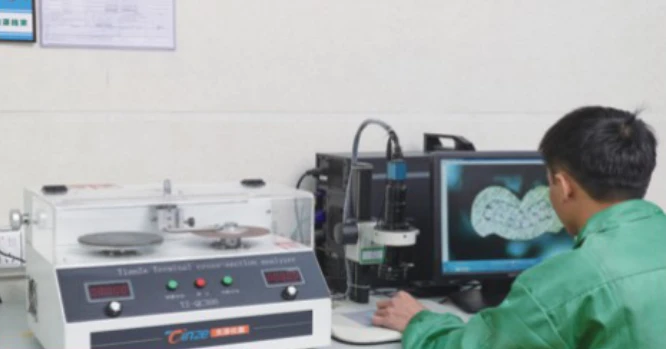
Terminated Ends
Cross-section inspection examines the crimp structure and section geometry of the selected wire and terminal combination against agreed criteria.
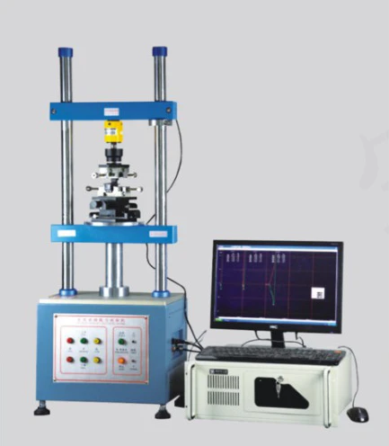
Connector Mating
Insertion and withdrawal testing assesses the selected branch connector and mating part under agreed conditions and force limits.
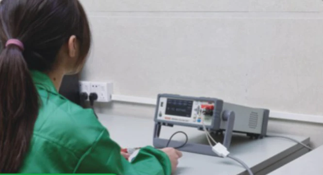
Selected Electrical Paths
Resistance measurement assesses the selected path between agreed endpoints under the stated measurement conditions and compares the result with the agreed limit.
Inspection Request
| Check | Order reference | Requirement to include |
|---|---|---|
| Branch geometry / identification | Branch layout and drawing revision | Measurement datum, path, cable condition, limits, inspection quantity and record |
| Termination | Wire / terminal / branch-end references | Criteria, sample quantity and record |
| Connector mating | Branch connector / mating-part references | Conditions, force limits, sample quantity |
| Selected resistance path | Network / endpoint references | Method, conditions, limit, inspection quantity and record |
Inspection scope and records form part of the order agreement. Where records are included, each result should be linked to the relevant wire and terminal, branch end, mating pair, endpoint pair or drawing revision.
Include Inspection RequirementsBranched Harness RFQ
Send the existing drawing, BOM or sample details with the required quantities. The optional sheets below organise missing branch-layout, connection and inspection information.
Branch Layout & End Schedule
Record the main run, breakout positions, branch endpoints and covering boundaries.
Editable HTML / print to PDF
Download Branch Layout SheetHarness RFQ Worksheet
Reference the BOM, circuit allocation, drawing revision, quantities and requested checks.
CSV worksheet
Download Harness RFQ WorksheetExisting drawings and schedules can be referenced directly. The worksheets are customer requirement templates, not JTY product drawings or test reports.
Contact Us
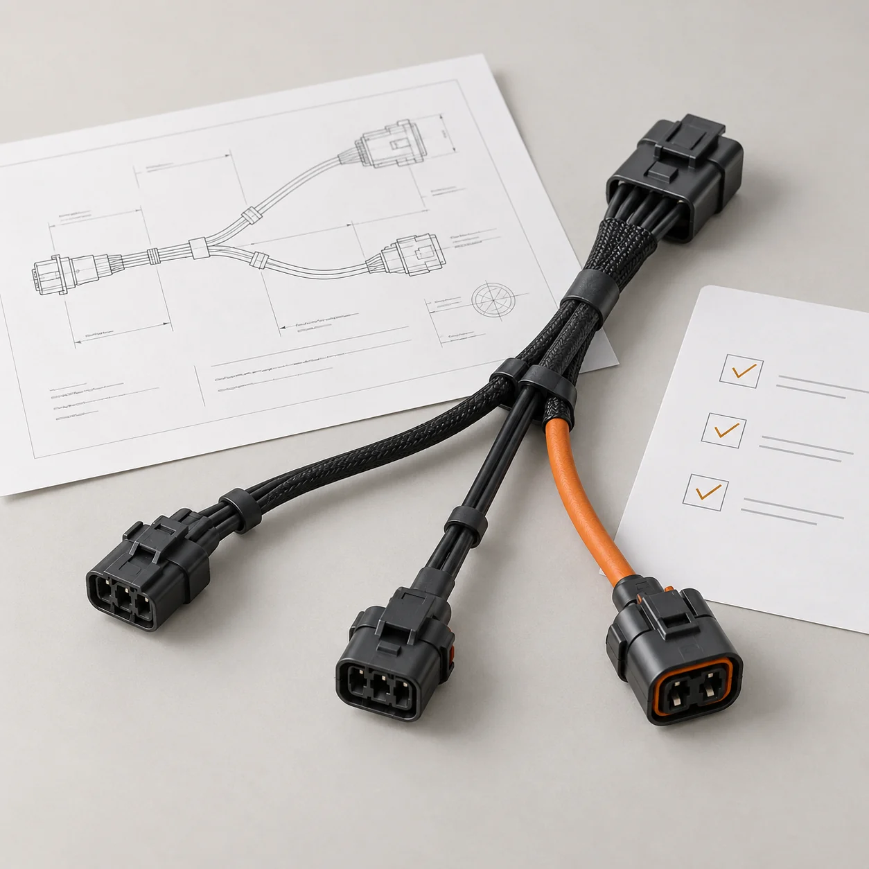
Tell JTY about your connector, wire harness or cable assembly project. Share the drawings, specifications or sample details you have for an initial review.
 Your Project