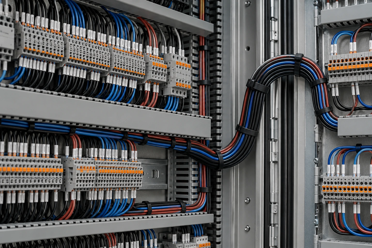
Generated control-cabinet wiring concept.
Control Panel Harness Constructions
Compare branched housing harnesses and mixed-end lead assemblies. Product illustrations are based on JTY samples.

Match the Wire End to the Terminal
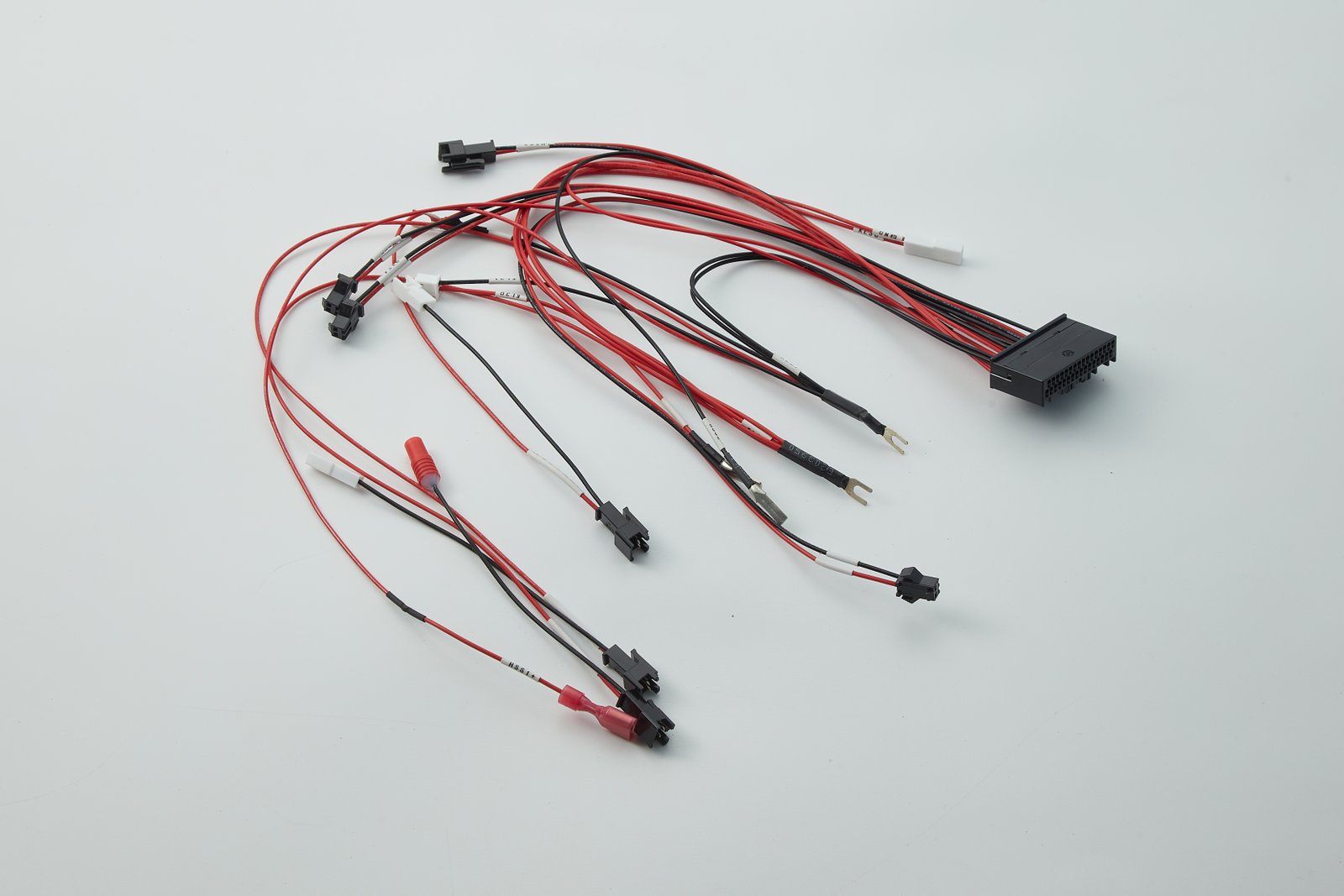
The equipment connection determines the required end preparation. Record End A and End B separately, including the parts used at each end. The sample end structures do not establish a match to the Phoenix Contact reference below.
Compare the End Structures
Housing end
Conductors entering connector housings
Housing and contact part numbers, mating reference and cavity assignment
Ferrule
Metal tubes with red insulating collars
Target equipment terminal, conductor size and ferrule part number
Fork terminal
Open-ended metal terminals on individual leads
Terminal part number, equipment fastener size and connection orientation
JTY sample details.
Phoenix Contact PT 2,5
Part number 3209510
 Phoenix Contact PT 2,5 connection data
| Flexible conductor | 0.14–4 mm² |
|---|---|
| Flexible conductor with ferrule, without plastic sleeve | 0.14–2.5 mm² |
| Flexible conductor with ferrule, with plastic sleeve | 0.14–2.5 mm² |
| Stripping length | 8–10 mm |
Phoenix Contact lists the general connection range and directly pluggable range separately. Selecting a conductor within the general range does not establish that it meets the directly pluggable condition.
Directly Pluggable Connections
| Ferrule without plastic sleeve | 0.5–2.5 mm² |
|---|---|
| Ferrule with plastic sleeve | 0.34–2.5 mm² |
For this terminal, 0.25 mm² falls within the listed range for flexible conductors with plastic-sleeved ferrules. It falls below the 0.34 mm² minimum listed for direct insertion under that condition. These published values apply only to this terminal, not to JTY harness ratings.
Keep Stripping and Ferrule Dimensions Separate
The terminal's stripping requirement and the ferrule's barrel length are separate entries. The termination specification records both. Housing ends also need the contact's conductor range and preparation requirements.
End A and End B each need an equipment or mating reference, end-part numbers, wire specification and termination requirements.
Discuss End RequirementsTurn Connection Points into a Wire List
Each wire-list row links a source terminal to a target terminal and records the wire and finished end treatments. Use the same wire ID on the BOM, markers and inspection record.
Example connection W101 runs from terminal 1 on X1 to terminal A1 on K1. The identifiers are illustrative and are separate from the ABK photograph.
End treatment and marker text belong to the same connection record as the source and target. This lets the BOM, wire list and drawing refer to the same conductor during quotation and inspection.
- Kit ID
- CP-01
- Drawing revision
- B
Put Manufacturing Data on the Same Wire Record
| Field group | Information carried with each connection |
|---|---|
| Wire | Wire specification, cross-section and colour |
| Length | Cut length, measurement datums and tolerance |
| End A / End B | Termination type, end-part numbers and cavity or terminal designation |
| Marking | Text at each end, reading direction and position relative to the termination |
| Order reference | Assembly part number, drawing revision, kit ID and quantity |
Dimension the Installation Route
The schematic defines the electrical connections. The route drawing defines the physical layout used to specify wire lengths and branches. The illustrations do not specify a bend radius or flex life; movement requirements belong in the project specification.
Fixed Cabinet Route
Wires routed through cabinet ducts need a defined path between their terminations. Branch locations and tail lengths describe where the assembly leaves that path.
| Drawing entry | Measurement detail |
|---|---|
| End datums | Named reference point at each termination |
| Route length | Length along the specified path between the datums |
| Branch position | Distance from a stated datum to the breakout |
| Tail length | Distance from the breakout to the stated end datum |
| Tolerance | Permitted variation for each controlled dimension |
Overall, branch and tail dimensions need their own datums and tolerances. Movement requirements belong with the cabinet-door route.
Specify the Kit and Ordered Quantity
Define the order unit before comparing quotations. Individual leads, assembled harnesses and cabinet kits carry different quantities and supply boundaries. Grouping and packaging are part of the agreed supply scope.
| Proposed order unit | What the order line defines |
|---|---|
| Individual lead | One wire reference and its finished end treatments |
| Harness assembly | One assembly part number covering the specified branches and ends |
| Cabinet or functional kit | One kit ID listing the required assemblies, leads and loose items |
Separate Kit Content from Order Quantity
Illustrative order calculation
- Kit ID
- CP-01
- Drawing revision
- B
- Leads per kit
- 12
- Ordered kits
- 10
12 leads per kit × 10 kits = 120 assembly leads
2 additional leads for W101
120 assembly leads + 2 spare leads = 122 leads
Keep Loose Items and Customer-Supplied Parts Visible
The BOM records the quantity per kit for each assembly and loose item. Spare leads remain separate order lines. Customer-supplied housings or contacts need their own part references and quantities.
Record the kit-list revision and the applicable assembly-drawing revisions on the order. Record branch or end-part changes in the kit content even when the ordered kit quantity stays the same.
Agree the Acceptance Records
Inspection records need the same assembly or kit ID as the order. The drawing revision identifies the requirements used for acceptance. Test methods, limits and record coverage are defined by the agreed project scope; the tests listed below are not automatic requirements for every harness.
| Inspection item | Acceptance basis | Record content |
|---|---|---|
| Connections | Approved source-to-target map and defined isolated circuits | Connection pairs covered by open- and short-circuit checks |
| Identification | Approved wire IDs, end markings and cavity assignments | Marking and cavity checks against the wire list |
| Dimensions | Drawing datums and tolerances for overall, branch and tail lengths | Measured values for the controlled dimensions |
| Terminations | Requirements for the selected contacts, ferrules and housings | Applicable crimp, contact-seating and housing-lock checks |
Dimensions
Dimensional-check illustration.Terminations
Crimp cross-section illustration. Acceptance limits apply to the specified terminal and wire combination.Separate Continuity from Other Test Requirements
Continuity checks use the defined connection map. Dielectric withstand, insulation resistance and pull-force tests need separate acceptance conditions.
| Additional requirement | Information needed in the inspection scope |
|---|---|
| Dielectric withstand | Test points, voltage, duration and pass criterion |
| Insulation resistance | Test points, test voltage and minimum resistance |
| Pull force | Terminal and wire combination, test method, sampling and acceptance force |
Carry the Order Reference into the Record
Illustrative record header| Kit ID | CP-01 |
|---|---|
| Drawing revision | B |
| Record fields | Inspection date / inspected quantity / applicable requirements / results / disposition |
Before the Drawing Is Released
What does a schematic or sample leave undefined?
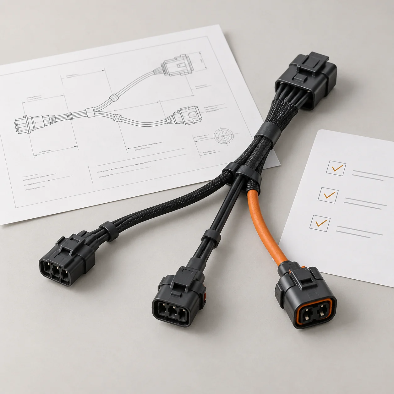
A schematic shows electrical connections but may not specify the physical route, finished dimensions or end-part references. A sample can show the existing construction, but the connections and dimensions to retain still need to be identified. Any intended changes need to be reflected in the manufacturing drawing.
How should a housing or contact substitution be approved?
Compare the exact mating references, cavity arrangement and contact wire range. Include the termination requirements in the comparison. Matching pitch alone does not establish interchangeability. Record an approved replacement in the BOM. Update the drawing revision wherever the replacement changes its requirements.
Contact Us
Tell JTY about your connector, wire harness or cable assembly project. Share the drawings, specifications or sample details you have for an initial review.
 Your Project