Energy Storage
Connectors and Wire Harnesses
JTY manufactures energy storage connectors, BESS and BMS wire harnesses and battery storage cable for battery modules, racks and cabinets. CN plug-in connectors carry 70A to 500A and bolt connectors 70A to 400A by model, both rated up to 1500V DC. Samples are ready in 3 to 7 days with the connector fitted to your harness. You check fit and temperature rise on the sample before batch production.
Energy Storage Connector and Harness Categories

High Current Battery Connectors
Plug-and-socket connectors for battery modules and racks.
CN06–CN14 · 70–500A · 10–185 mm²
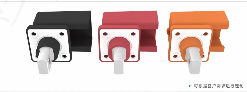
Battery Bolt Connectors
Panel-mounted connectors that take a cable lug on a bolt.
70–400A · 600/1500V DC · 10–120 mm²
High Voltage Battery Connectors
Plug-in and bolted connectors for high-voltage DC battery systems.
Up to 1500V DC
Waterproof Battery Connectors
Sealed connectors for exposed battery connection points.
CN series · IP67

BESS Wire Harness
High-voltage power harnesses for C&I storage racks, battery packs and combiner box input and output.
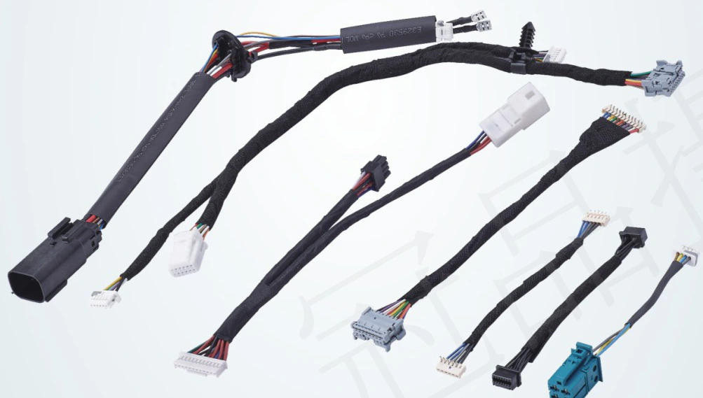
BMS Wire Harness
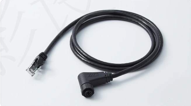
Voltage and temperature acquisition wiring for the BMS.
Battery Cable Assemblies
Battery cable assemblies from JTY are single-conductor PVC or silicone cables with a crimped ring lug at each end.
Compare Connection and Wiring Options
The plug and socket connect and disconnect at the module. Suits modules that are installed, replaced or serviced on site.
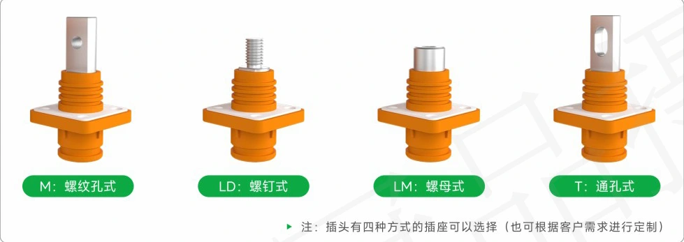
70–500A by model · 1000/1500V DC · IP67 · ≥500 mating cycles · straight or right-angle plug · stud, nut, threaded-hole or through-hole socket
A cable lug bolts to the connector, and the outlet rotates 360° to follow the cable route. Suits fixed connections that stay in place for the life of the equipment.
70–400A by model · 600/1500V DC · screw torque M6 5.5 N·m, M4 2 N·m
Tests Behind the Ratings
Send Your Drawing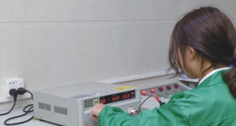

| Test | What it checks | Checked against |
|---|---|---|
| Withstand voltage | Dielectric strength | CN 3000/4000V AC; bolt 2200/4000V AC |
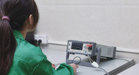
| Precision resistance | Contact resistance | CN ≤0.2 mΩ at 100 mA |
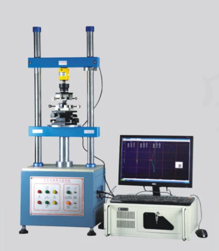
| Mating cycle | Mating force and life | CN ≤75 N, ≥500 cycles |
| Electronic load | Temperature rise at rated current | Your temperature-rise limit |
| Crimp cross-section | Terminal compression | The terminal maker's crimp specification |
| High/low temperature aging | Operating temperature range | CN −40 to 125 °C |
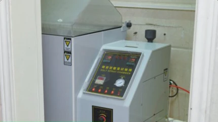
| Temperature-humidity and salt spray | Environmental exposure | Your exposure conditions |
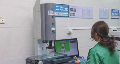
| 2D optical measurement | Dimensions | Your drawing |
Plan a Battery Rack Power Connection
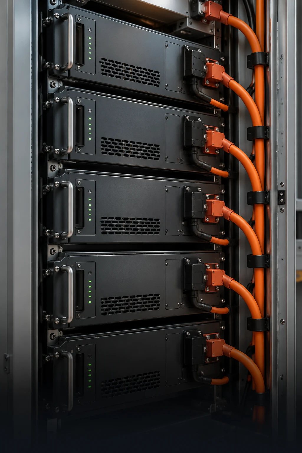
In this rack layout, a plug connects at the module and ring terminals bolt to the DC busbar.
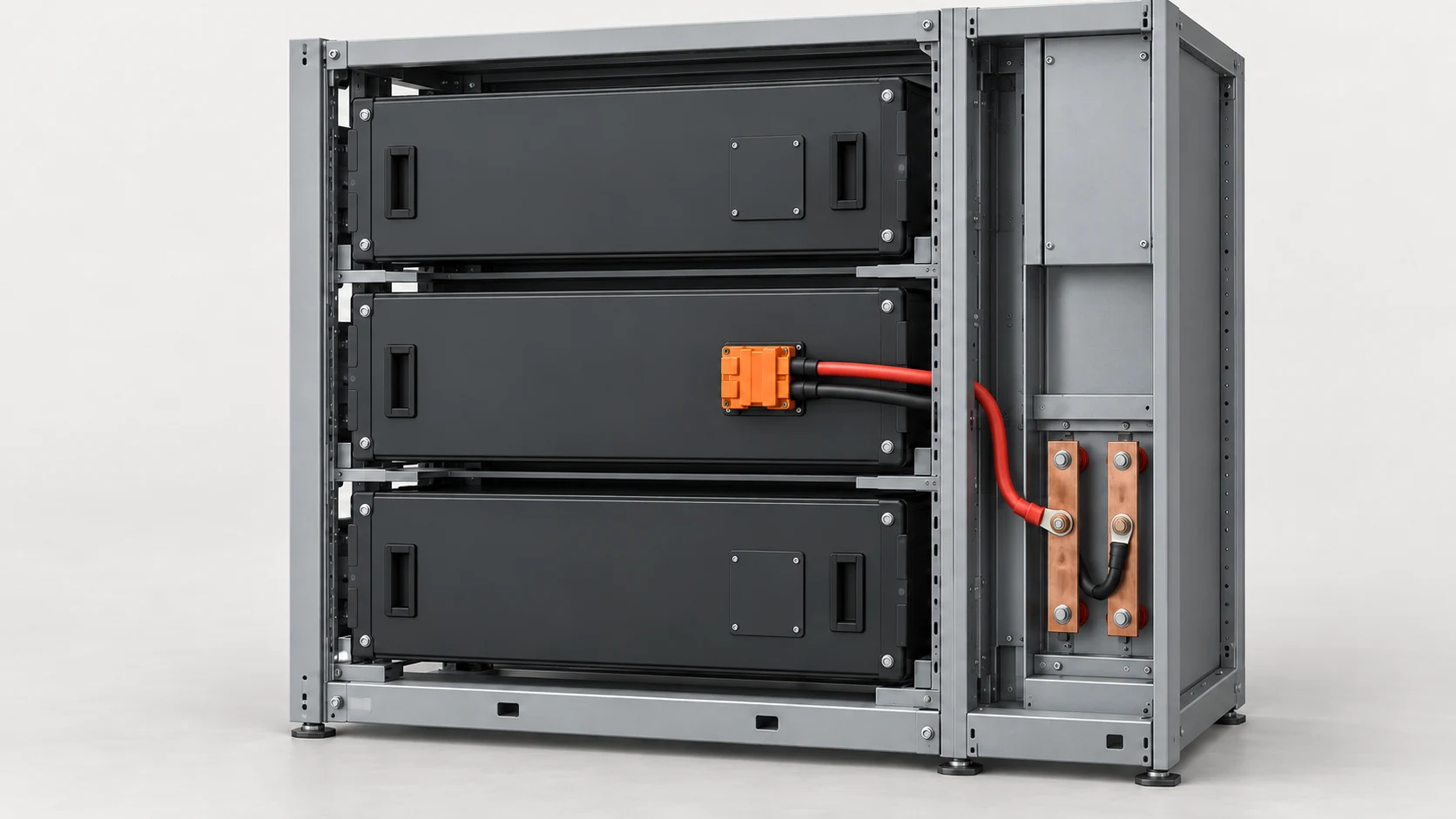
The plug mates with the front-facing module interface. The service side needs room for full mating and release.
The power pair runs down the side channel to the DC connection. Support points and bend radius keep cable weight off both ends.
Two ring terminals bolt to separate DC points. Lug size and orientation follow the busbar drawing.
What the Sample Check Covers
- 01Current and temperature
- JTY tests the connector, cable and terminals as one power path at your load and cabinet temperature, against an agreed temperature-rise limit.
- 02Fit and service access
- Fitted in your rack, the sample shows full mating, flat terminal contact, bend clearance and module removal with the surrounding equipment in place.
- 03Polarity and labels
- Power polarity and cable labels follow the rack wiring diagram.
Ordering Information

Samples
Ready in 3 to 7 days once the configuration is agreed. Sample and courier fees are quoted with the sample.

Minimum order
100 pieces.

Lead time
Batch production takes about 30 days after order confirmation.

Tooling
Overmolded exits that need a new mold carry a separate mold charge.
Contact Us
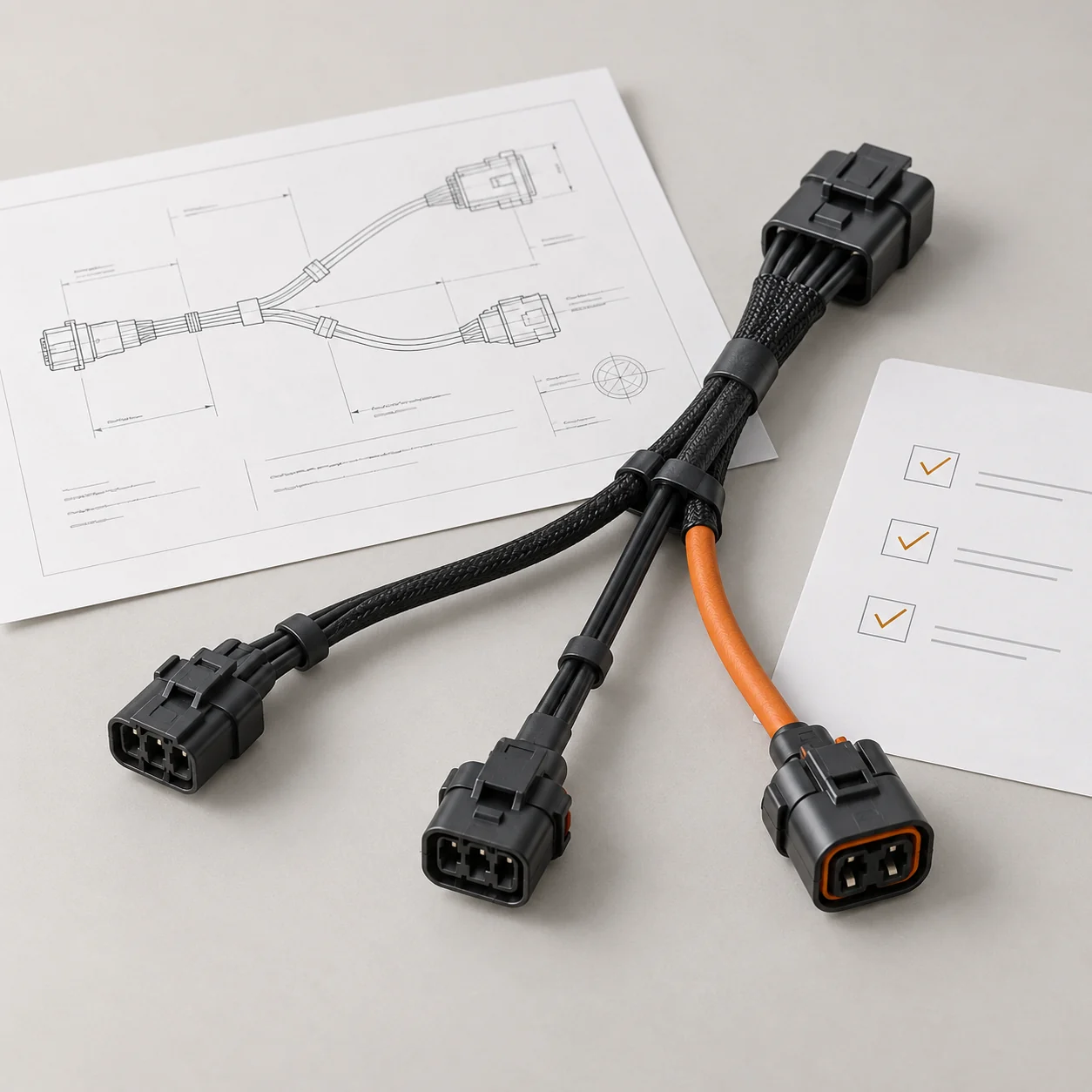
Tell JTY about your connector, wire harness or cable assembly project. Share the drawings, specifications or sample details you have for an initial review.
 Your Project