Servo Power & Feedback Cable Forms
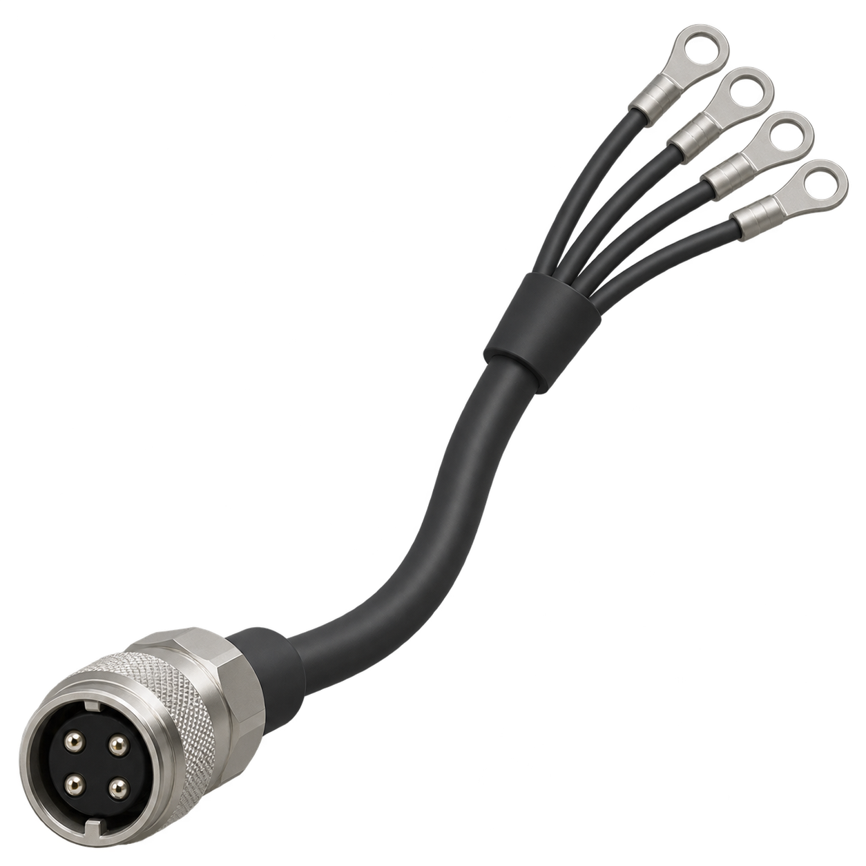
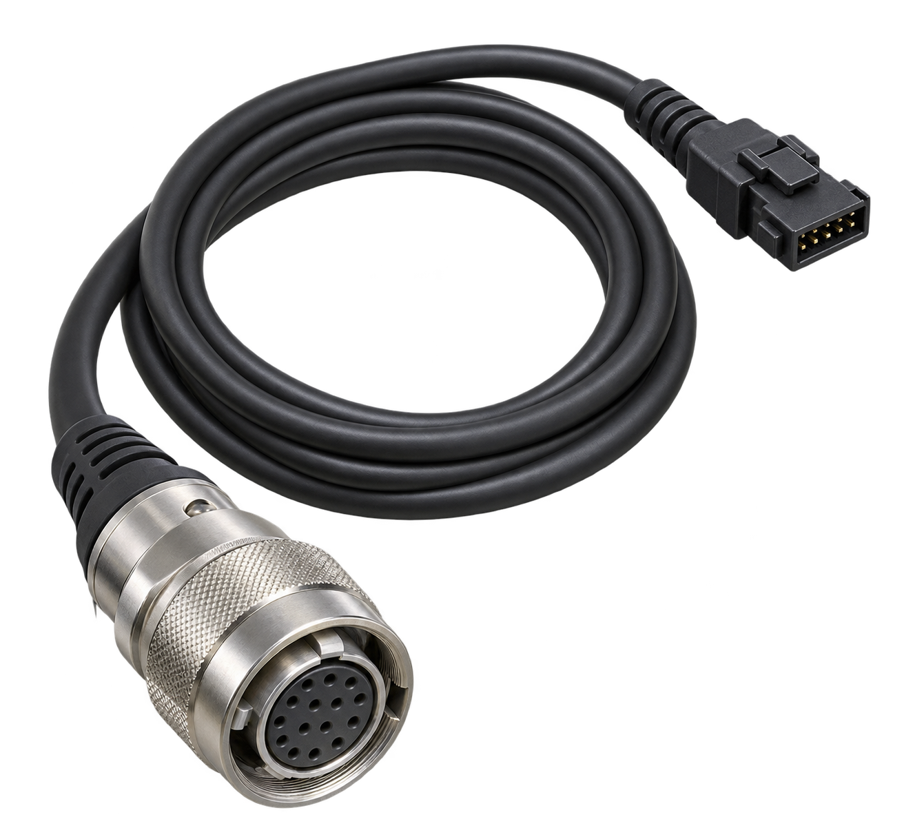
These illustrations compare a motor-end connector with individual leads, plug-ended feedback, and feedback with a battery branch. JTY supply scope and system compatibility require project review.
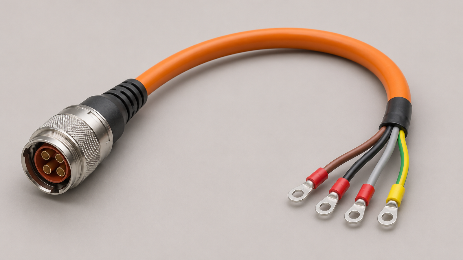
Motor Power Cable Assembly
A circular motor-end connector and individual leads show one way to connect a motor power circuit to the drive-side termination. The drive-side end treatment follows the equipment connection.
Discuss Motor Power Cable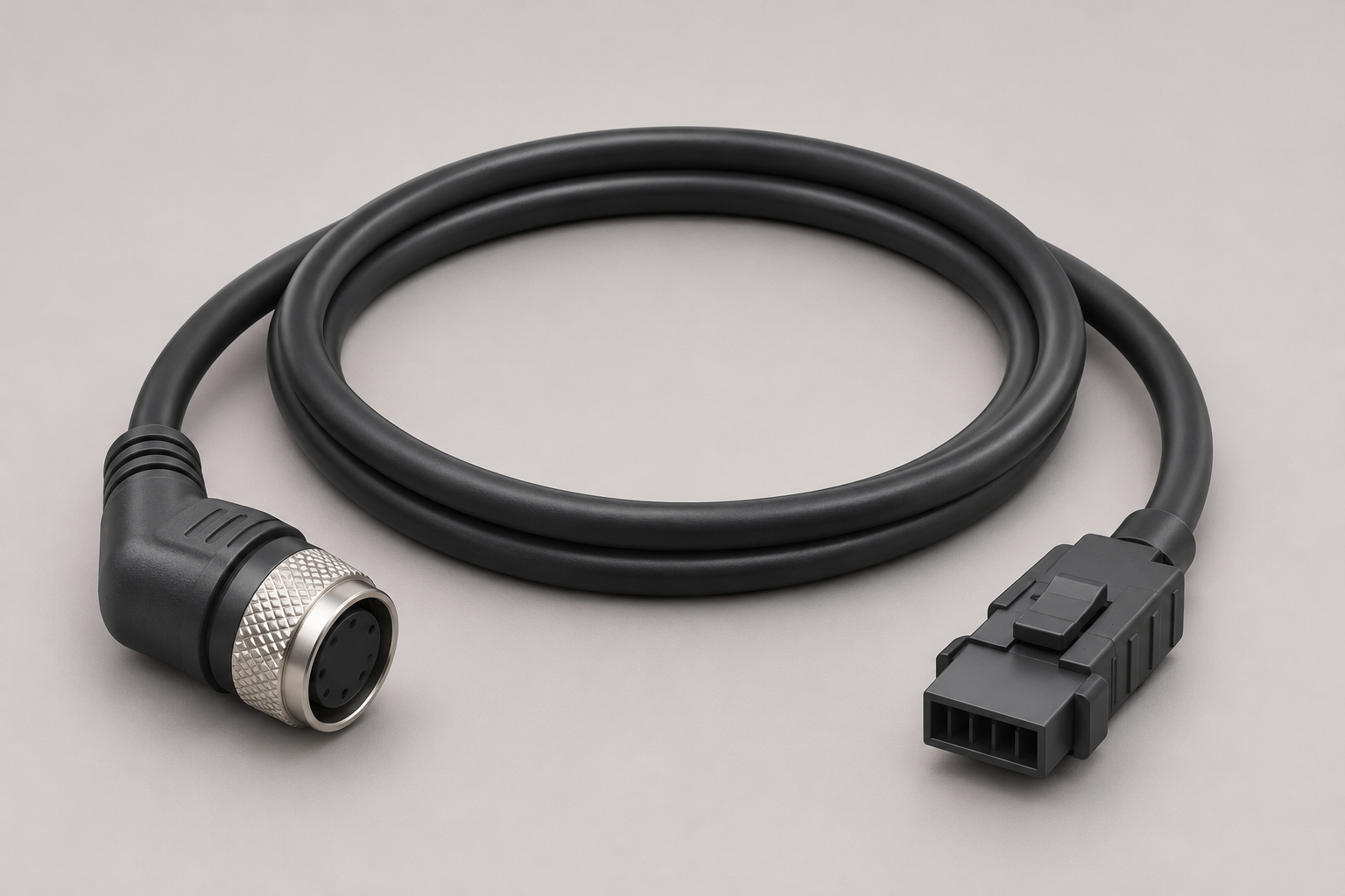
Encoder Feedback Cable
A connector-ended cable links the motor feedback device to the drive.
Discuss Encoder Cable
Encoder Cable with Battery Branch
A separate battery-holder branch provides a connection for an encoder system that uses an external battery.
Discuss Battery-Branch CableMatch the Drive, Motor & Cable Arrangement
For each axis, the motor and drive, feedback interface and brake option provide a common basis for comparing cable arrangements. Replacement selection starts with the original cable reference.
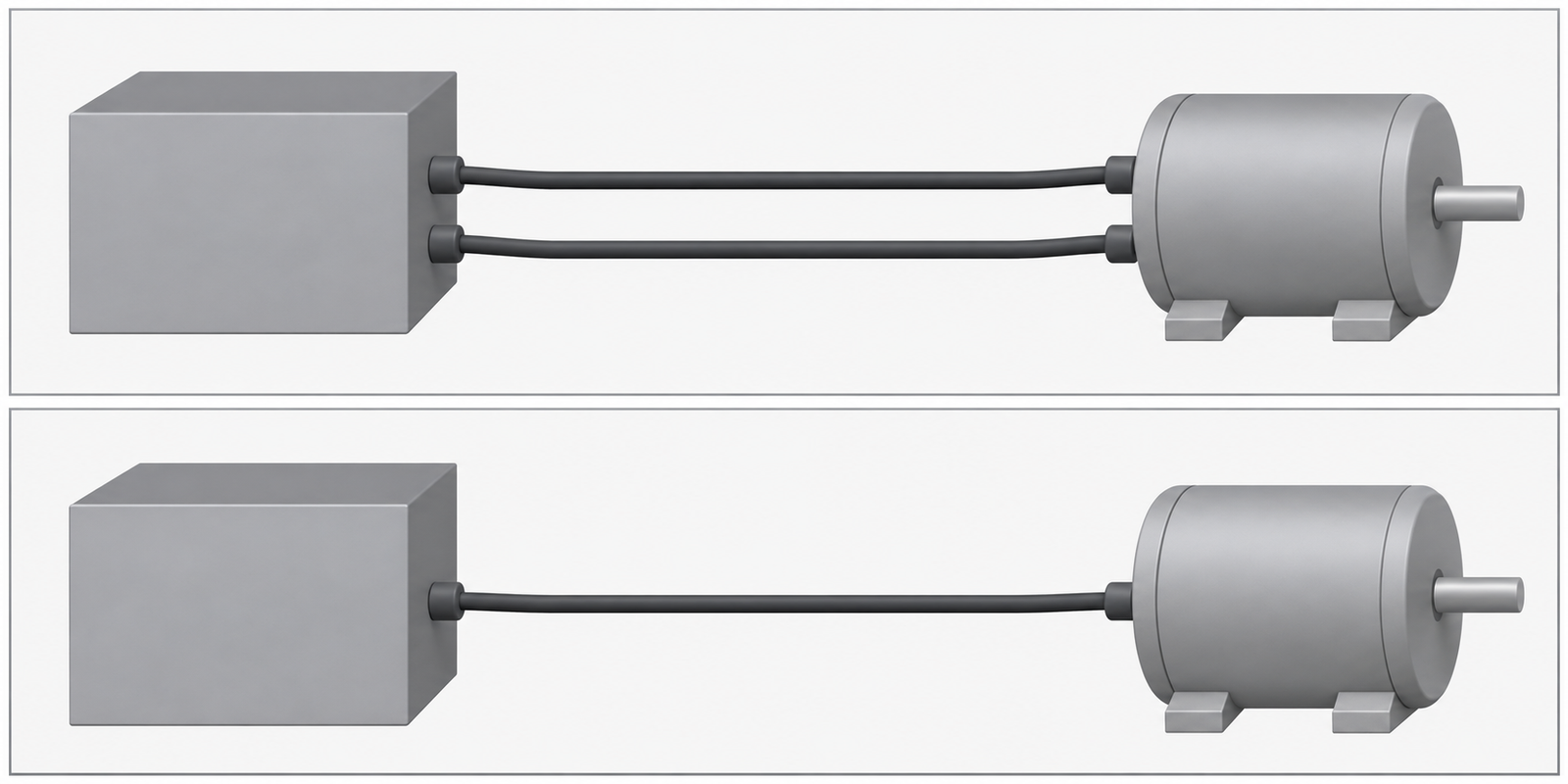
Separate or combined cable
Separate arrangements use distinct power and feedback cables. A combined cable brings conductors into one cable only where the selected equipment and cable construction support that arrangement.
- Power circuit
- Motor-end connectors and drive-end connections define the two ends. Include the motor's required protective-earth connection in the drawing.
- Brake option
- A motor with a brake may need separate brake connections. The brake supply requirements are checked separately from the motor power circuit.
- Feedback interface
- The drive must support the feedback device’s interface and protocol; select the cable arrangement for that system.
- Battery connection
- For an encoder system requiring external battery backup, select an arrangement that includes the required battery connection.
Specify Cable Length, Conductors & Shielding
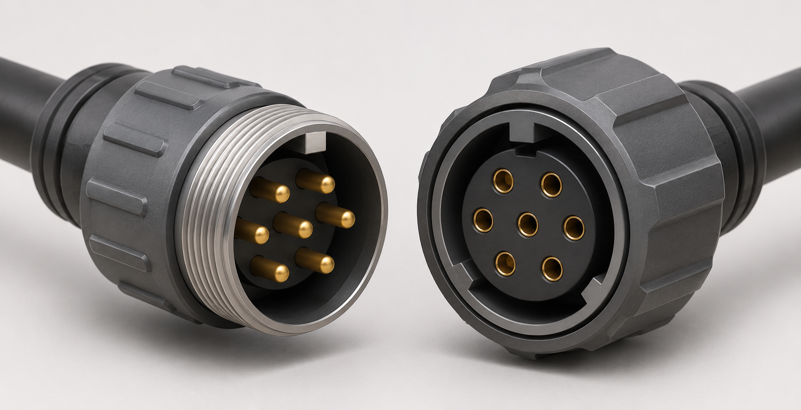
Connector fit and electrical mapping are separate checks. A matching connector shape does not establish contact assignment, conductor pairing or compatibility between the motor and drive.
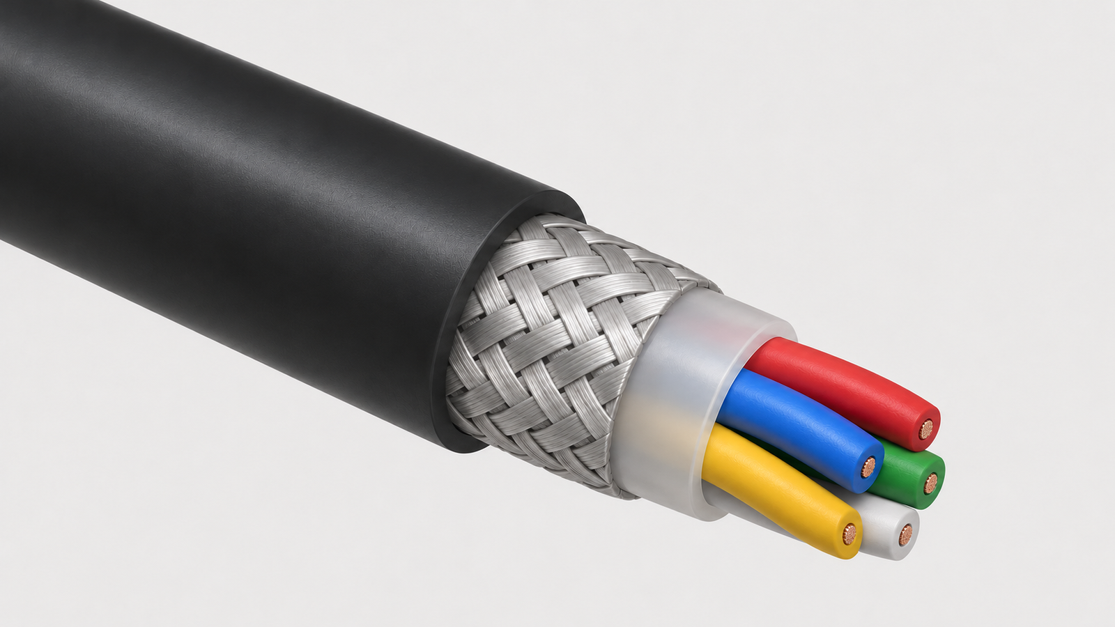
- Power and brake conductors
- Voltage, current and installed length are inputs to conductor selection. Connector-contact and terminal limits are checked alongside the cable conductors.
- Feedback supply and signal pairs
- Supply voltage at the encoder can become a constraint on a longer route. Preserve the interface's specified signal pairing and electrical properties when considering a replacement.
- PE, shield and feedback GND
- Treat protective earth, shield termination and feedback supply return as separate connections, following the selected equipment instructions.
The cable BOM identifies the cable reference, conductor sizes and pair arrangement. The assembly drawing defines shield connections, length measurement points and project tolerances. Material substitutions must be considered against the cable BOM, the assembly drawing and the selected system's complete-path requirements.
Select the Construction for the Installed Motion
Fixed installation, repeated bending and torsion impose different requirements. Compare a selected cable's documented life with the required life only under the applicable installation and test conditions.
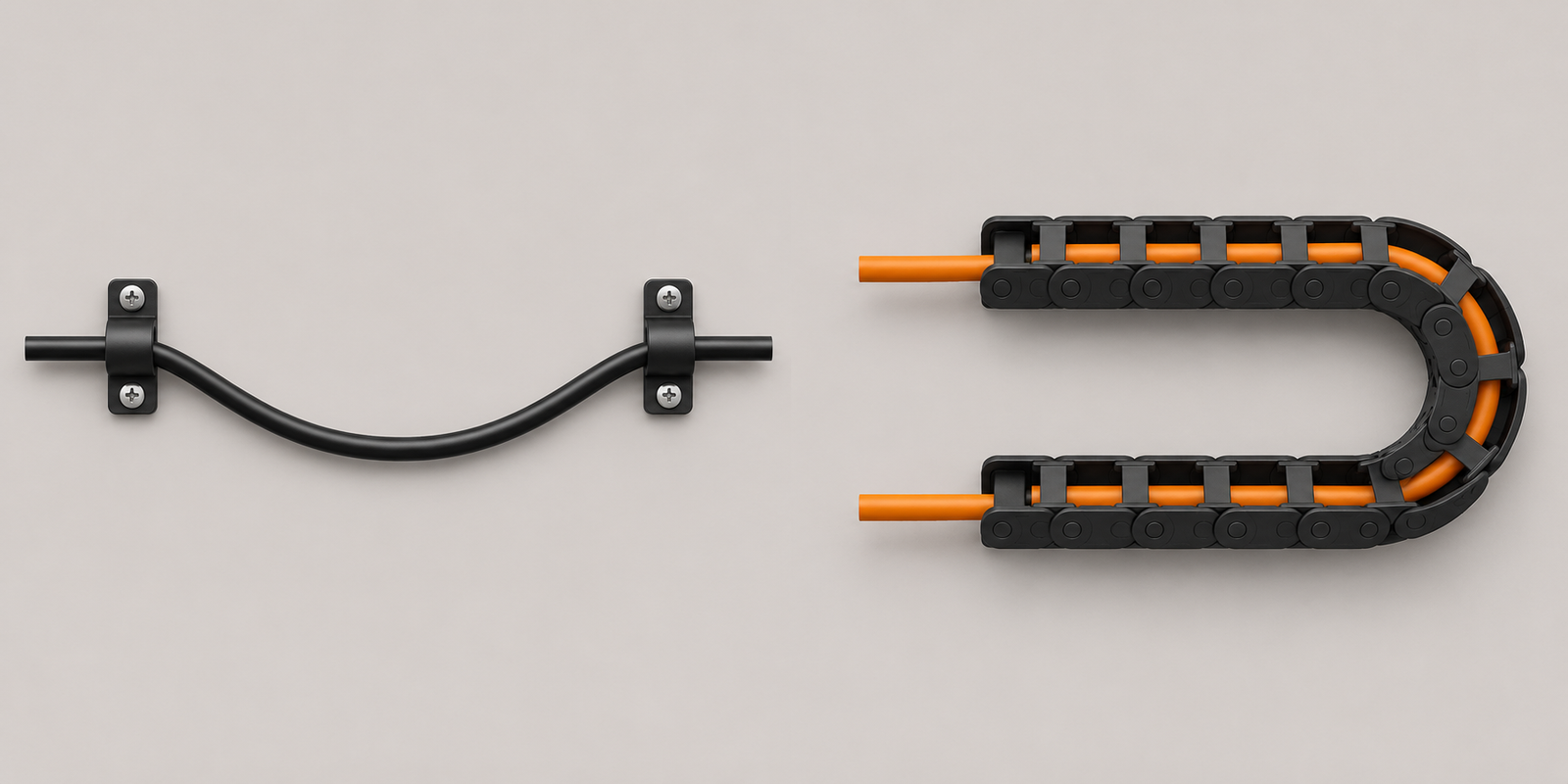
- Fixed installation
- The installed route sets the actual bend and connector exit direction. Check the available bend against the selected cable’s permitted radius, including movement during operation or servicing.
- Linear cable chain
- Cable outside diameter and chain radius define the installed bend ratio. Travel, speed, acceleration, temperature, end restraints and the free-moving length are part of the comparison.
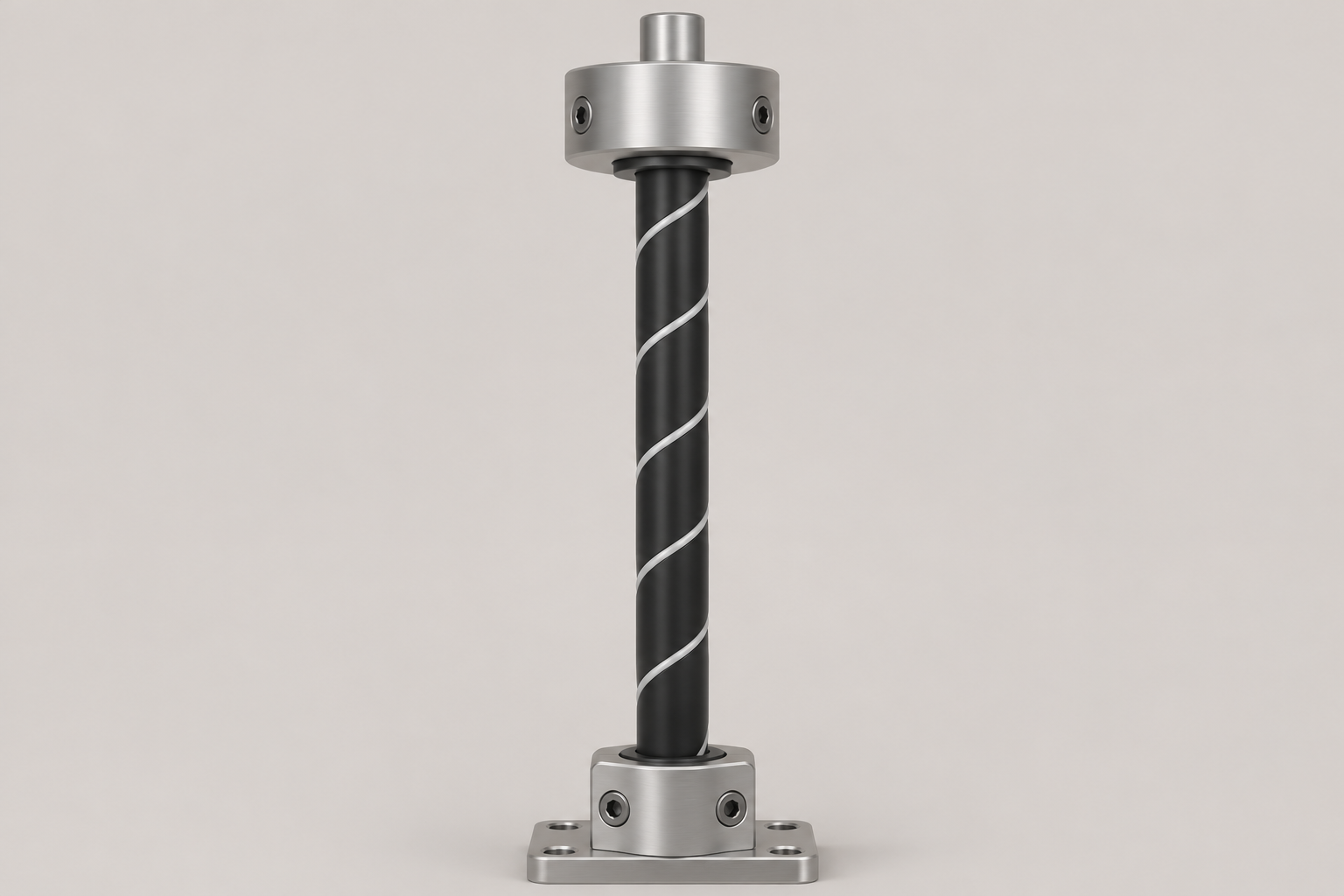
Torsion in the route
Twist angle, active cable length and any combined bending describe the torsional duty. A bending-cycle claim alone does not establish torsion performance.
The selected cable’s minimum bend radius must suit its installation; a rating from a different cable does not establish suitability.
Define the Drawing & Sample Acceptance
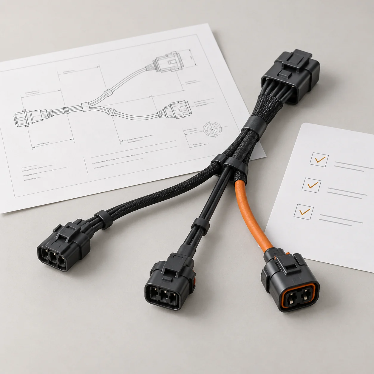
The approved drawing and netlist provide the basis for accepting the assembly. The project defines the acceptance criteria and records, while motor-and-drive operation is verified separately.
Interface and installation fit
The approved drawing identifies both connector references, mating-face viewing direction and contact numbers.
It also defines straight or right-angle forms, installed exit directions and available space at the motor and drive, with branch lengths and holder positions measured from the specified length reference points.
The pin-to-pin netlist defines signal pairing, brake connections, protective earth and shield termination; the drawing or supply scope identifies any supplied mating parts.
Assembly checks
Compare dimensions, continuity and wiring with the approved drawing.
The inspection records identify the assembly or batch checked.
Any insulation or withstand test uses project-agreed points, voltage, duration and limits, taking electronic components into account where present.
Installed-system verification and delivery
Feedback recognition, brake operation and the defined motion duty require verification on the motor and drive by the party assigned in the project.
Continuity alone does not establish system compatibility.
The agreed delivery scope identifies sample and batch quantities, permitted substitutions, labels, packing and required documents.
Contact Us
Tell JTY about your connector, wire harness or cable assembly project. Share the drawings, specifications or sample details you have for an initial review.
 Your Project