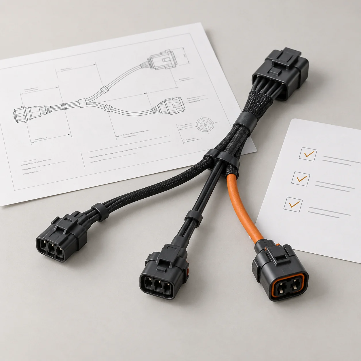
JTY assembly example
Cable Assembly Examples
Compare the end connections and termination formats in these JTY assembly examples.
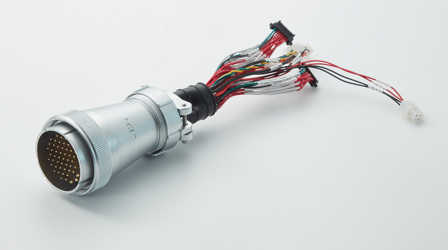
Multi-Contact Breakout Harness
End AMulti-contact circular plugEnd BLabelled branches with compact connector housings and terminal endsSeveral labelled branches meet at a multi-contact plug. Map each branch destination on the assembly drawing.
View Photo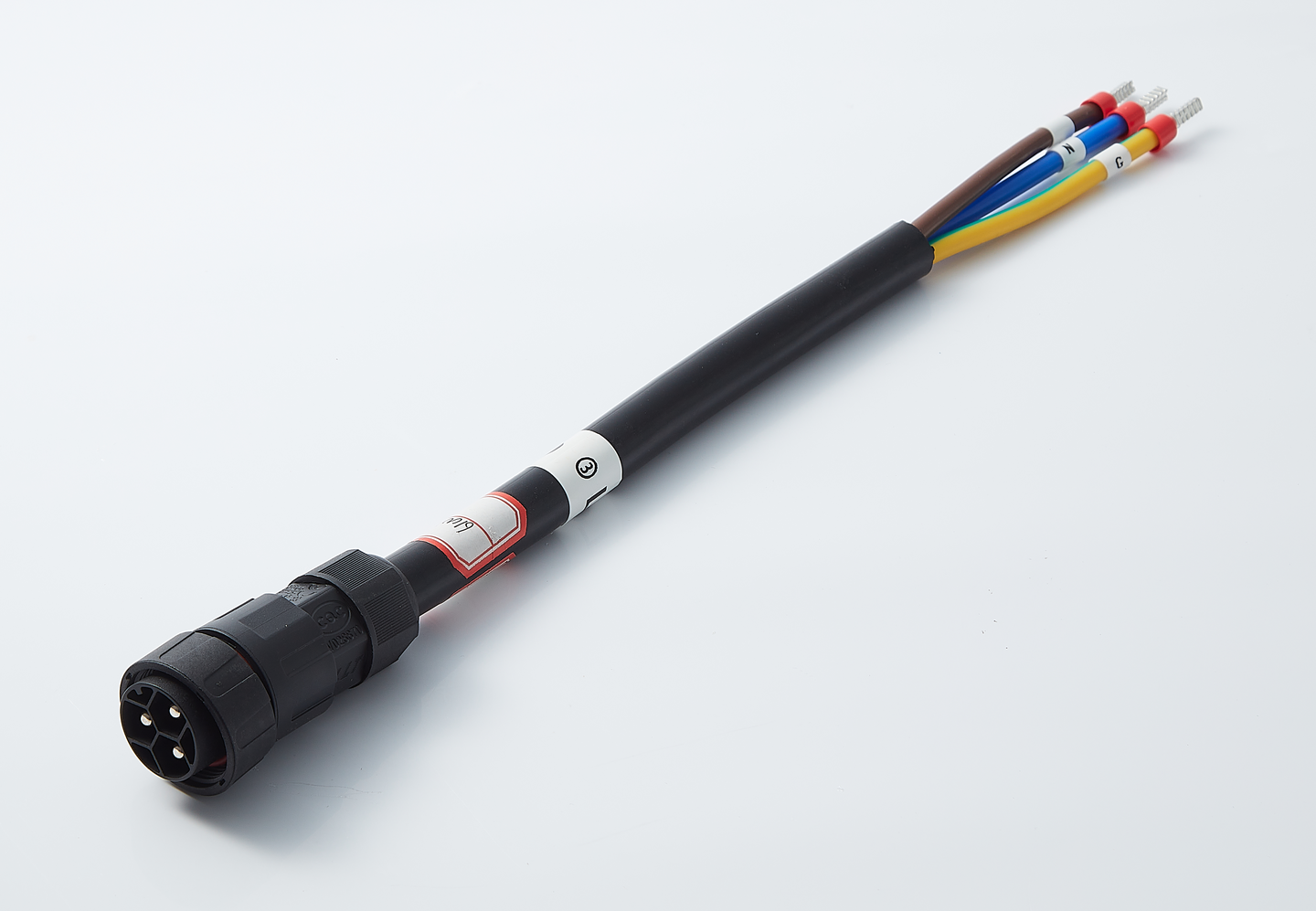
Circular Plug to Ferrule Leads
End ACircular plugEnd BIndividually labelled ferrule leadsFerrule ends require equipment terminals that accept the specified conductor and termination. Select the ferrule size and contact length against the equipment terminal instructions.
View Photo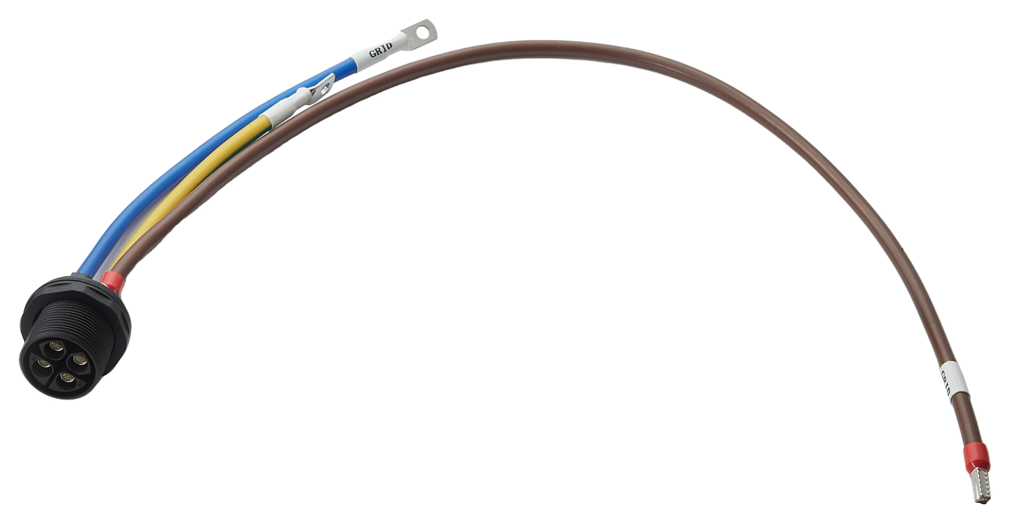
Circular Receptacle with Ring and Ferrule Leads
End AThreaded circular receptacleEnd BRing-terminal and ferrule leadsMatch ring-terminal holes to the equipment stud or bolt size. Specify ferrule dimensions against the receiving terminal. Add the receptacle mounting detail to the equipment drawing.
View PhotoController, Joints & Tool Connections
Compare each connection as a separate assembly or as part of a wider harness. The drawing or sample establishes the interfaces and the work included in the quoted unit.
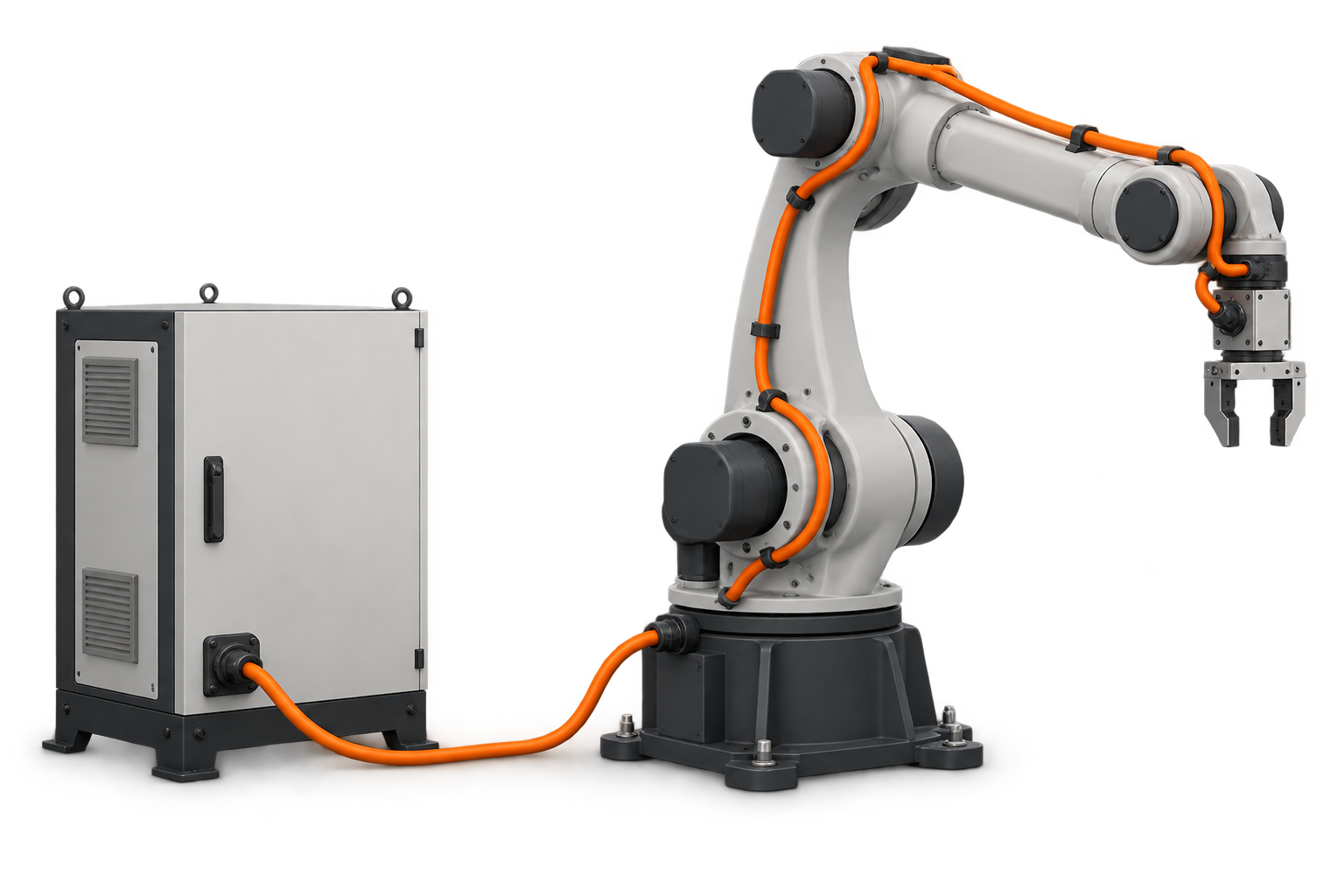
A controller-to-base lead can be quoted as a separate assembly between the two specified interfaces. JTY builds the lead to the agreed drawing or sample, using the connectors listed on the drawing or supplied by the customer. The quotation identifies the finished ends and any end agreed to be supplied unfinished for equipment-side termination.
The drawing identifies the reference points used for the finished lead length.
An arm-internal harness can combine the power, brake and feedback circuits shown on the drawing. The quoted assembly identifies its branches, finished ends and required shield terminations. JTY assembles the specified or customer-supplied connectors; the equipment design defines the interfaces and the division between fixed and moving sections.
The drawing records connector orientation and cable exit direction.
Where the equipment design already has a wrist disconnect, the segment between that point and the tool can be quoted as a separate replacement or purchase. The quotation identifies its tool-side connector, circuits and branches. The equipment owner or OEM determines whether that existing break point permits the segment to be replaced independently.
The customer checks connector location and wrist clearance on the sample and shares any required drawing changes.
Cable Data for Bending & Torsion
The examples below compare cable manufacturers’ stated conditions for different motion types. JTY can source the wire and connectors specified on the drawing, or use alternatives approved by the customer. The selected cable and required end and shield terminations define the quoted assembly; availability of a named cable is confirmed for the order.
| Manufacturer / Cable | Part / Construction | Outside Diameter | Bend Radius | Torsion |
|---|---|---|---|---|
| LAPP ÖLFLEX ROBOT 900 P | 0028160; 4G0.75 mm² | 6.6 mm nominal | Flexible use: 15D; fixed: 4D | ±360°/m |
| LAPP ÖLFLEX ROBOT 900 DP | 0028135; 4 × 0.34 mm²; spiral tinned-copper shield | 5.7 mm nominal | Flexing: 15D; fixed: 4D | ±180°/m |
| igus chainflex CFROBOT2 | CFROBOT2.07.04.C; 4 × 0.75 mm²; overall shield | 8.0 mm maximum | e-chain: 10D / 80 mm; flexible: 8D; fixed: 5D | ±180° over a 1 m cable length |
| HELUPOWER ROBOFLEX HYBRID-D PUR UL/CSA | 11022484; (4G1.5 + (2 × 0.5)D)D | 10.3 mm approximate | Torsion: 10D; fixed: 5D | Up to ±180°/m; 5 million cycles minimum; maximum 180°/s and 60°/s² |
D denotes the cable outside diameter. Each radius applies to the manufacturer’s named use condition.
The HELU entry follows its datasheet dated 19 August 2024.
The examples have different conductor arrangements and are not interchangeable part recommendations. These cable data do not establish the finished JTY assembly’s motion life.
Check the Space at the Moving Section
For LAPP part 0028160, 15 × 6.6 mm gives 99 mm for the catalogue’s flexible-use entry. The fixed-installation entry gives 26.4 mm. Both use the nominal diameter and their stated use conditions; the fixed radius is not the moving-section criterion. The customer checks the available space along the joint route. Cable length, fixed points and finished ends enter the agreed drawing for the quoted assembly.
Read Cycle Counts with Their Conditions
A cable manufacturer’s cycle value applies to its stated test conditions. JTY can perform bending or torsion checks agreed for the project, with motion, active length, mounting positions, cycle target and acceptance criteria specified in the order. Equipment service-life validation remains a separate assessment; a catalogue cycle figure alone does not establish the finished assembly’s service life.
Drawing Release & Trial Fit
The drawing and sample establish the finished assembly, the equipment-side work and the checks agreed for the order.
Pass-Through & Termination Sequence
Whether the finished connector can pass through the narrowest opening determines the installation sequence. When both ends fit, the drawing can call for a complete lead. If an end needs termination after pass-through, JTY and the customer assess the drawing or sample and agree the feasible supply and equipment-side termination before quotation. The customer checks clearance on the sample.
Supply Boundary
The quoted BOM identifies the cable assembly, specified connectors and any customer-supplied parts included in the unit. A harness drawing may also refer to carriers, hoses or brackets outside that unit. The quotation identifies any separately agreed items and quantities, giving purchasing a defined scope to compare.
Assembly Checks & Equipment Validation
JTY checks the sample against the wiring schedule, dimensions and connector orientation agreed for the order. The equipment owner, OEM or integrator checks installation and movement on the robot and shares trial-fit findings.
JTY and the customer review any resulting changes to lead or branch length, connector orientation or termination. The approved sample and agreed drawing revision define the subsequent production build.
Replacement & Extension Questions
Existing disconnect points and the robot’s service instructions determine the replacement boundary. Identify the affected assembly and both adjoining interfaces.
Permitted cable lengths and extension combinations depend on the robot and controller documentation. Cable type, total run length and every added connector need review before an extension is specified.
Contact Us
Tell JTY about your connector, wire harness or cable assembly project. Share the drawings, specifications or sample details you have for an initial review.