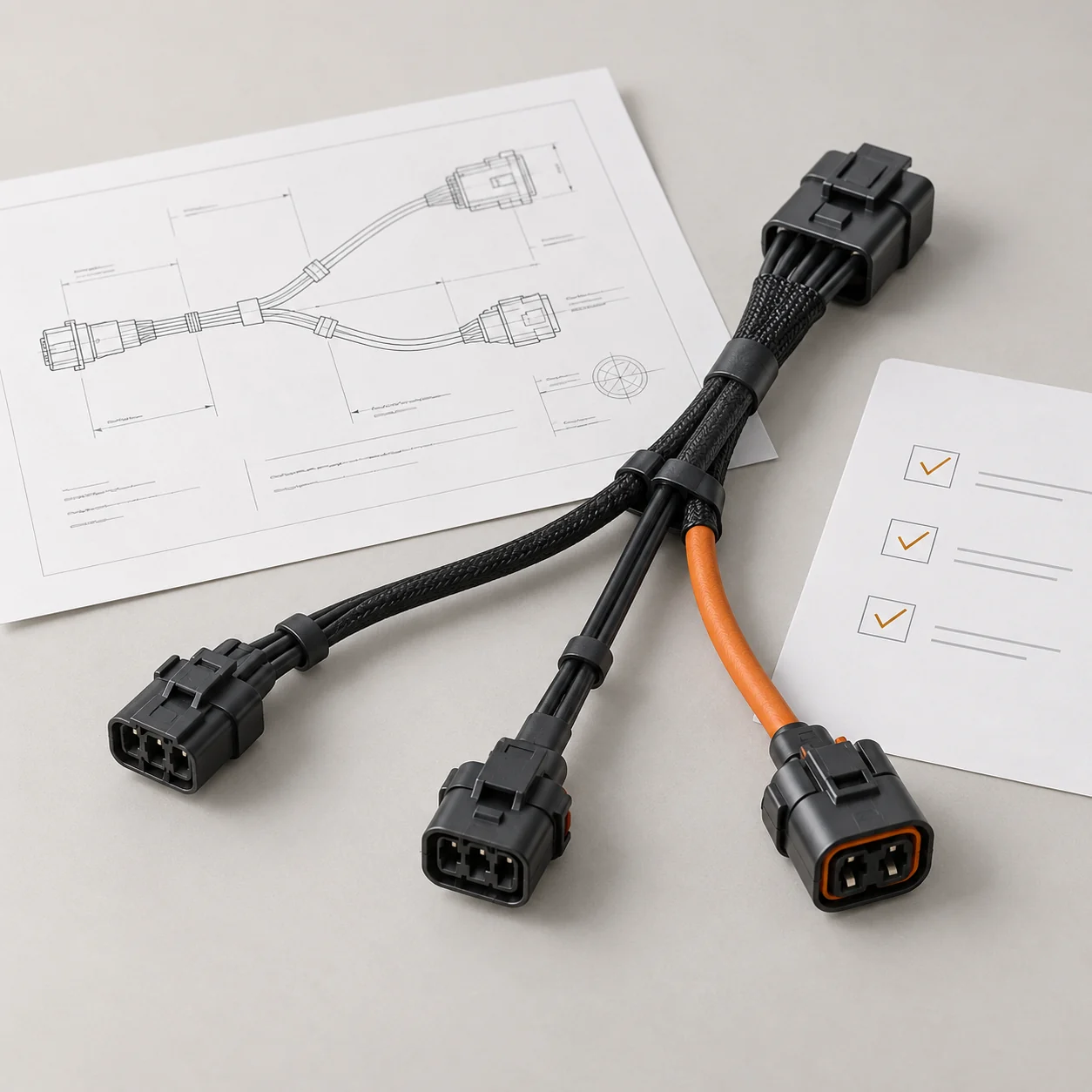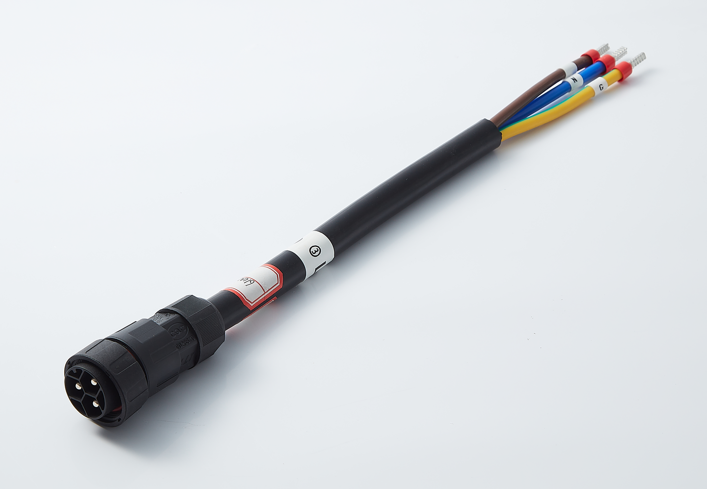
JTY circular plug and ferrule-lead assembly example.
Cable Assembly Examples
Compare the connector and terminal ends in these JTY assembly photographs.
Circular Plug to Ferrule Leads
End ACircular plugEnd BIndividually labelled ferrule leadsMatch the ferrule dimensions to the receiving equipment terminal.
View Photo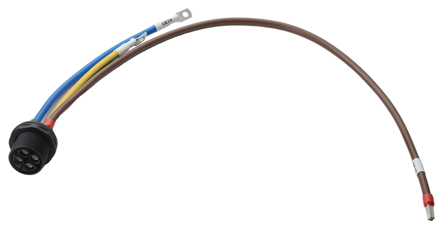
Circular Receptacle with Ring and Ferrule Leads
End AThreaded circular receptacleEnd BRing-terminal and ferrule leadsInclude the receptacle mounting detail and the receiving terminal references in the drawing.
View Photo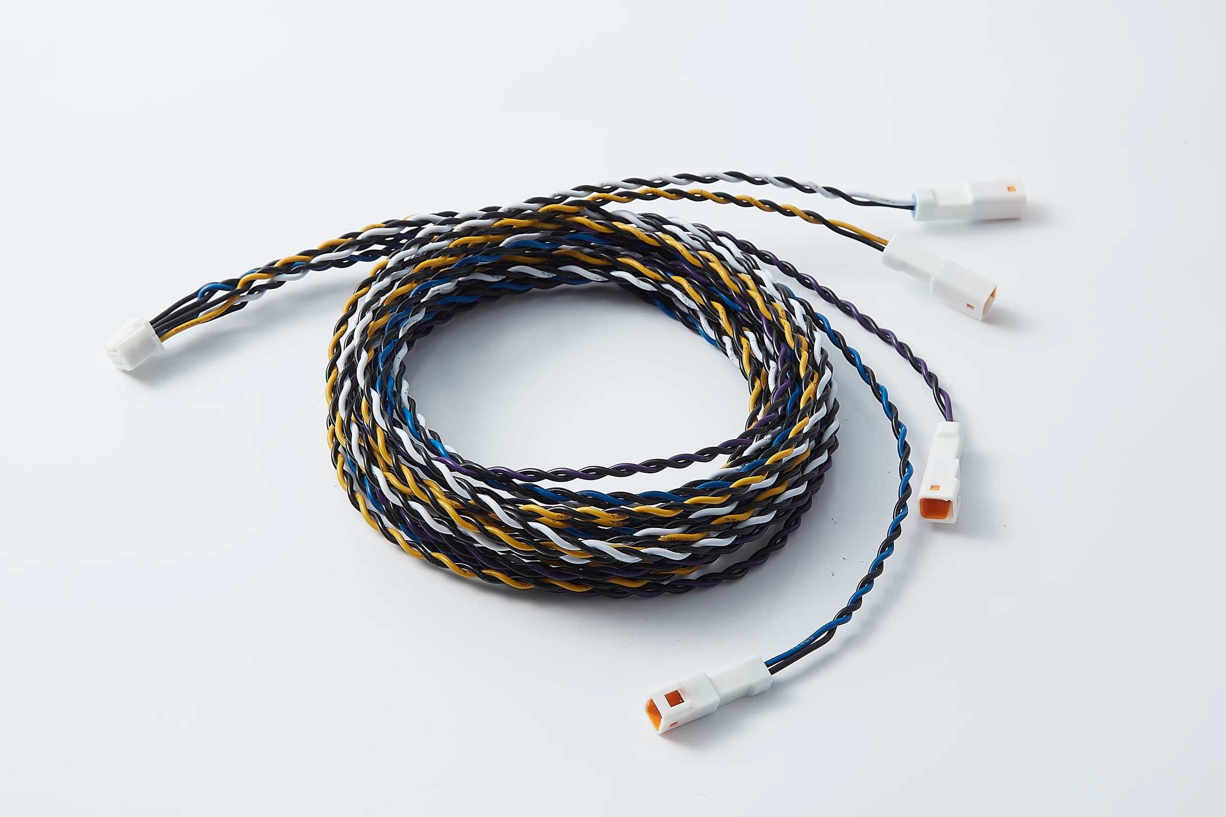
Compact Connector Lead Set
Wire arrangementTwisted-wire groupsVisible endsCompact connector housingsIdentify the housing reference and destination for each termination in the cable schedule.
View PhotoPhotos show assembly structures. Robot and tool interfaces are defined for each design.
Match the Robot and Tool Interfaces
Robot and tool interfaces determine the cable ends, pin assignments and the power path. Once the equipment interfaces are identified, JTY can quote the finished cable section to the drawing or sample.
Pin contacts
Socket contacts
Use the equipment drawing to identify the mating references, keying and connector-face viewing direction.
Robot and Connector Version
The equipment owner identifies the robot and tool versions, mating references, connector gender, keying and face-view direction. JTY can source the wire and connectors specified on the drawing or assemble customer-supplied connectors; availability of a named part is confirmed for the order.
OEM interface referencesUR introduced a female e-Series tool connector on 1 September 2024; the robot serial number identifies the applicable version. RealMan’s third-generation tool connectors have distinct red-dot and blue-dot keying, and the manufacturer requires matching versions. These examples show why the named interface matters before JTY sources or assembles a specified connector.
Pin Functions and Communication
The wiring schedule specifies supply, ground, signals and required shield termination with the equipment document revision. Agreed sample checks can include continuity, polarity and pin assignments against that schedule.
OEM interface referencesDoosan’s M/H Series V3.2.0 manual identifies two M8 eight-pin flange connectors, X1 and X2, with different I/O assignments. The equipment owner identifies the selected port and wiring; JTY terminates the lead to the agreed pin schedule.
Tool Power or Separate Supply
The equipment owner compares operating and start-up loads, peak duration and repetition against the robot and tool manufacturer’s supply limits. When a separate supply is needed, its cable is a distinct item to price alongside the tool lead. JTY builds the agreed cable path; the equipment owner remains responsible for the power-system decision.
The quoted scope identifies the tool lead, any separate supply lead and their finished ends. The equipment owner checks robot supply limits and selected connector contact ratings separately.
| Robot | Typical current, single pin | Typical current, dual pin | Peak current |
|---|---|---|---|
| UR3e | 600 mA | 600 mA | 2000 mA |
| UR5e | 1000 mA | 1500 mA | 2000 mA |
The published peak limit is 1 second at a maximum 10% duty cycle. The average over 10 seconds must remain within the typical current.
These values describe the named robot interfaces. They do not establish the current rating of a JTY cable assembly.
Tool and Peripheral Connection Paths
Separate the cable assemblies needed at each endpoint from the equipment they connect. The three paths below show how a tool, camera or changeable tool set affects the unit and quantity to quote.

Grippers and Tool Sensors
Robot tool I/O → selected gripper or tool sensor
Tools that require a control box follow the tool manufacturer’s connection arrangement.
The robot-to-tool lead can be quoted as a finished assembly with the specified connector at each end. If the tool uses a control box or an independent supply, the additional power or communication cable is a separate line item rather than an assumed part of that lead.
The equipment owner defines the tool, robot or control-box endpoints and their interface references. Control boxes, power supplies, software and tools are equipment purchases outside the cable assembly.
The connection diagram and bill of materials distinguish the tool lead from each additional cable, with finished ends, part references and quantities for comparison.
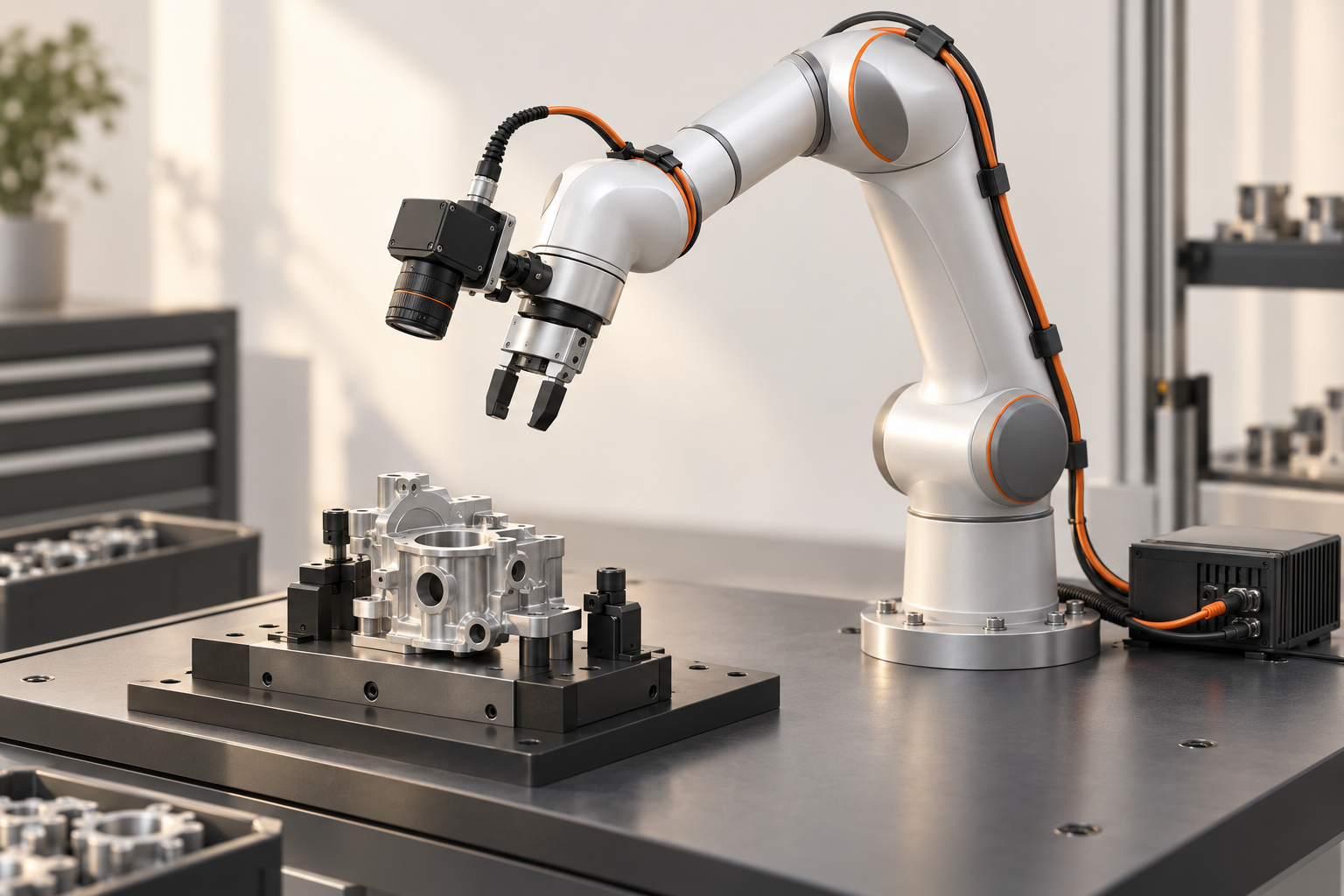
On-Arm Vision
Robot-mounted camera → required power and data equipment
Camera power and data leads can each be quoted to their selected interfaces and the drawing. A lighting or trigger branch is included only when shown in the agreed assembly scope; otherwise its cable is listed separately.
An on-arm camera moves with the robot, while a fixed workcell camera does not. The equipment owner identifies the moving span, strain-relief position and required field of view before the route is released.
The assembly drawing identifies the camera cable ends, branch destinations and lengths. The installation drawing locates fixed and moving cable sections.

Tool Changing and Workcell I/O
Robot-side cable → agreed disconnect point → tool-side lead
Where the equipment already provides an agreed disconnect, the robot-side lead and each tool-side lead can be quoted as separate assemblies. Fixture or control-box I/O cables are listed separately when included in the purchase.
Count robot-side sets per robot, tool-side leads per tool and spare leads separately. The mechanical tool changer, hoses and brackets are equipment items outside the cable assemblies.
Part numbers and quantities distinguish each replaceable lead and its two connection points. The equipment owner or OEM confirms that the existing disconnect permits the intended replacement.
Cable Routing and First-Install Acceptance
The equipment owner checks the sample on the installed tool and through its operating positions. Feedback on the route and connector access can then be assessed against the assembly drawing.
Plug Orientation and Working Space
A straight or angled cable exit changes the space needed beside the tool, camera and mounting hardware. The equipment owner checks access for connection, tightening and removal during trial fit.
The agreed assembly drawing specifies the connector type and exit direction for the finished end.

Programmed Motion and Manual Guidance
The equipment owner checks cable slack, snagging, pinching and connector pull through programmed motion, manual guidance and the parked position. Clamp and strain-relief locations affect the required cable length between fixed points. The drawing can then distinguish the moving span from the fixed sections.
Trial-fit feedback identifies the poses checked and any proposed change to cable length, branch position or fixing points.
Release the Tested Tool Configuration
Tie trial-fit results to the specific robot, tool and cable sections tested. JTY and the customer review any proposed changes to lead or branch lengths, connector orientation or terminations. The approved sample and agreed drawing revision define the subsequent production build.
| Record | Details to include |
|---|---|
| Configuration | Robot and interface version; tool or camera model; robot-side and tool-side cable references. |
| Positions reviewed | Programmed movement, manual-guidance positions and tool parking pose. |
| Findings and changes | Cable interference, connector loading, plug access and drawing corrections. |
| Release | Trial-fit photographs or pose records, responsible equipment team and accepted drawing revision. |
The equipment owner or integrator carries out the installed-system evaluation. Agree the requested records and acceptance points for the project.
Tool Cable Questions
JTY can quote the lead described in your drawing or sample. Robotiq’s ACC-TRBLS-KIT-M8 lists male and female M8 breakout leads and a separate USB-to-RS485 converter. Its 24 V power supply is excluded. List the required lead, converter, power supply and software separately when defining a diagnostic setup.
JTY can quote a cable assembly to your drawing or sample. Zivid lists CAT-6A cable options of 5, 10 and 25 m. Its angled extender is 3 m long. It advises against female-to-female or other passive Ethernet extensions. Show the camera model, total cable run and every intermediate connection in the enquiry. Specify the manufacturer-approved arrangement.
Contact Us
Share the robot and tool models, the required cable sections and the quantity for your project. Attach the drawing, BOM or sample details available for review.