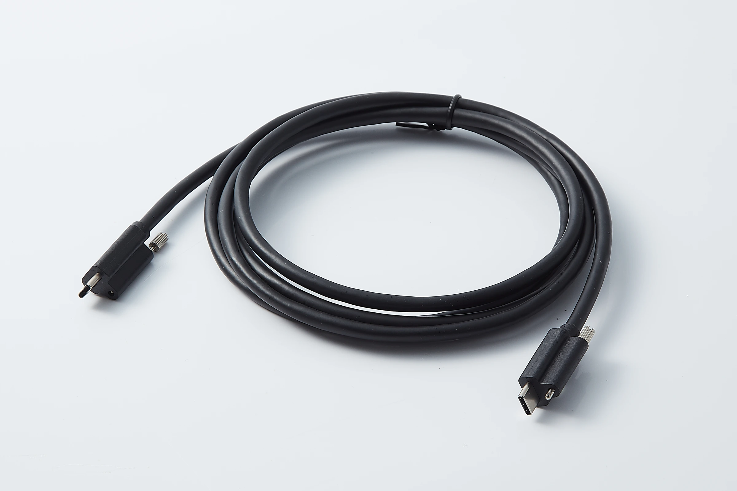
USB Cable Assembly Examples
Compare the connector ends and visible locking features in these JTY photographs. Camera compatibility and transmission performance require review of the selected assembly.
USB Type-C Cable Assembly with Locking Screws
USB Type-C plugs terminate both ends. Each plug has an adjacent locking screw. Match the plug envelope, screw position and mating port before choosing this structure.
Discuss the USB Type-C Assembly
USB Type-A to Micro-B Cable Assembly
USB Type-A and USB 3.0 Micro-B plugs terminate the black cable. The photographed ends have no visible locking screws. Check the camera port and its retention requirements.
Discuss the Type-A to Micro-B AssemblyCamera Connection Set
Camera data, power and control may use separate connections. Equipment models and interfaces determine the cable items in the system.
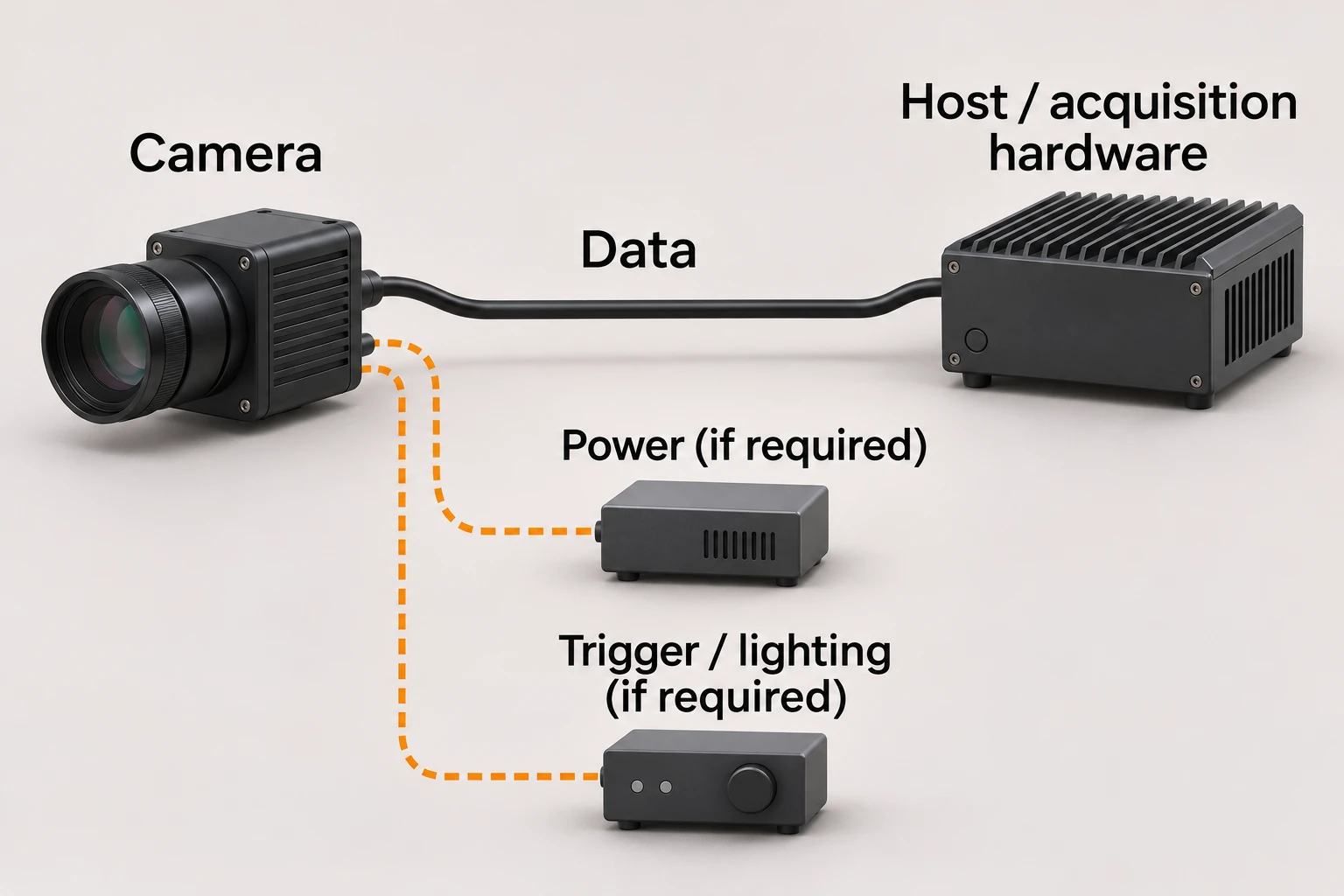
USB camera to host
A USB path carries data to the host and may power the camera when both devices support bus power. Trigger or lighting may need separate I/O.
- Data
- Camera USB connector type and host connector type.
- Power
- Camera power requirement and available host power.
- Control
- Sensor trigger and exposure or lighting signals assigned to the camera I/O port.
Cable Length and Camera Power
Cable selection depends on the entire installed path, camera load and power arrangement.
Passive copper
Insufficient source power can cause camera restarts or disconnections. Assess the camera load and available power across the complete installed cable path.
Active or optical paths
Converters, intermediate connectors and any auxiliary supply belong in the BOM. An optical data path alone does not provide electrical power to the camera.
Installed length
Record the length datums, cable segments, service loops and adapters on the drawing. Review the complete path with the camera and host under the intended operating settings.
Connector Fit and Cable Movement
Connector shape, retention and routing determine fit at the camera and host.
Type-C with locking screws
The adjacent screw needs a matching equipment fastening point. Include screw position, thread specification and tool access in the interface drawing.
Type-A and Micro-B without visible screws
The photographed ends do not show screw retention. The camera installation must define the required connector retention and cable strain relief.
Installation and movement

Fixed installation
Record connector exit, clamp positions, service loop, permitted bend radius and environment on the drawing.
Drag-chain bending
Record chain radius, travel, speed and cycle duty. Compare bending-life data only with its test conditions; screw retention does not establish cable life.
Robot torsion
Record rotating axis, twist angle, free length and combined bending. Drag-chain evidence does not establish torsion life.
Camera Power and Trigger Wiring
The ordered camera and connected-device manuals define pin assignments, electrical conditions and returns; contact count alone does not.
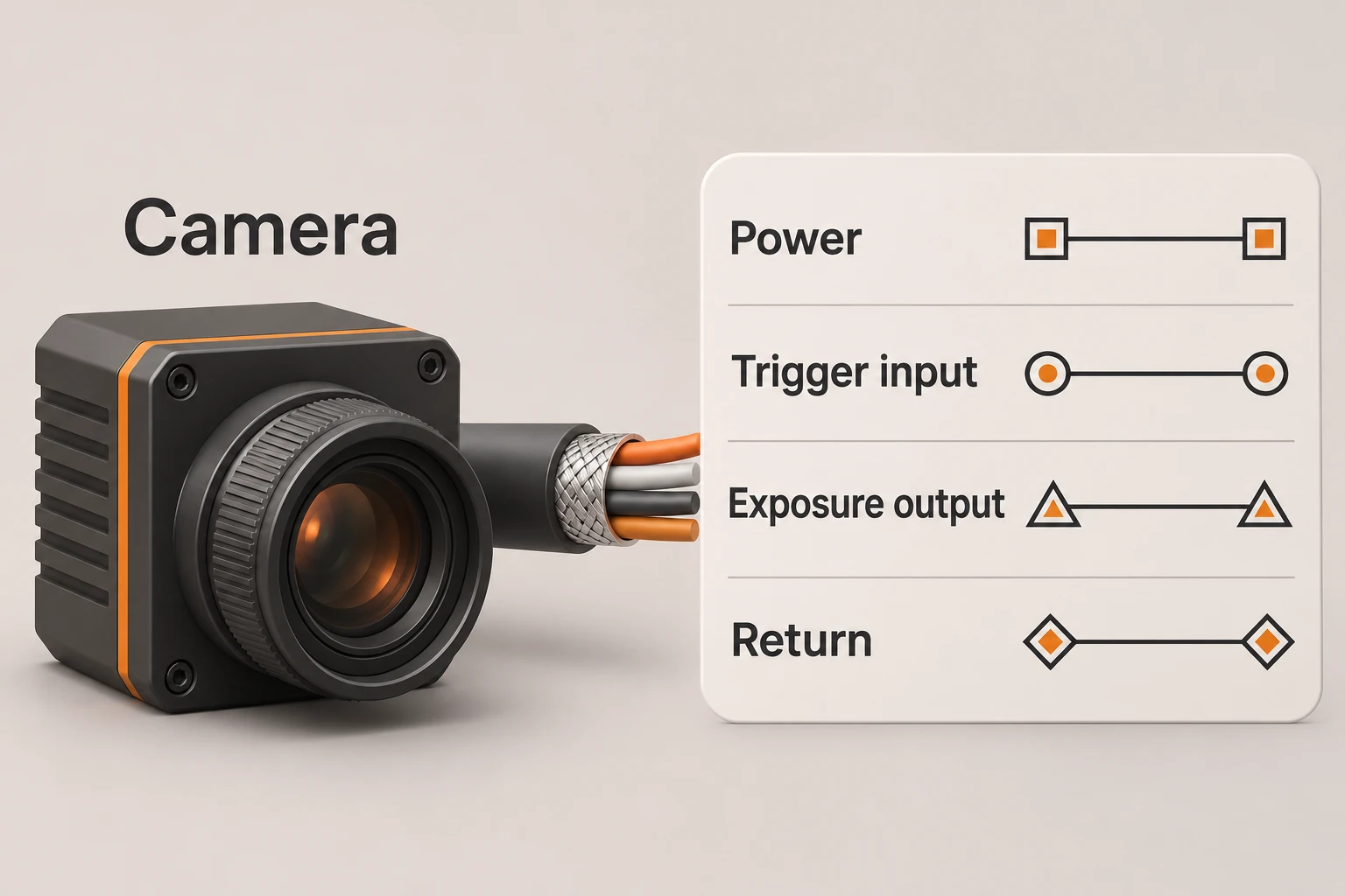
Point-to-point wiring schedule
- Equipment reference
- Camera model, connected device model and manual revision.
- Connector view
- Part reference, mating-face view and pin numbering.
- Signal mapping
- Pin, signal name, direction and destination terminal.
- Electrical conditions
- Supply or signal limits and the specified return path.
- Cable termination
- Wire identification, shield termination and unused conductors.
Wire colour alone does not establish a signal assignment.
Camera power
Distinguish a separate camera supply from data-path power, including the permitted input and return.
Trigger and exposure
Map each input and output to its destination with direction, level and return; distinguish trigger from exposure.
Lighting control
Identify the driving output and controller input. Separate control and light-power circuits when they use different connections.
Sample Acceptance
Agree on each check’s method, criteria, equipment, record and responsible party before sampling.
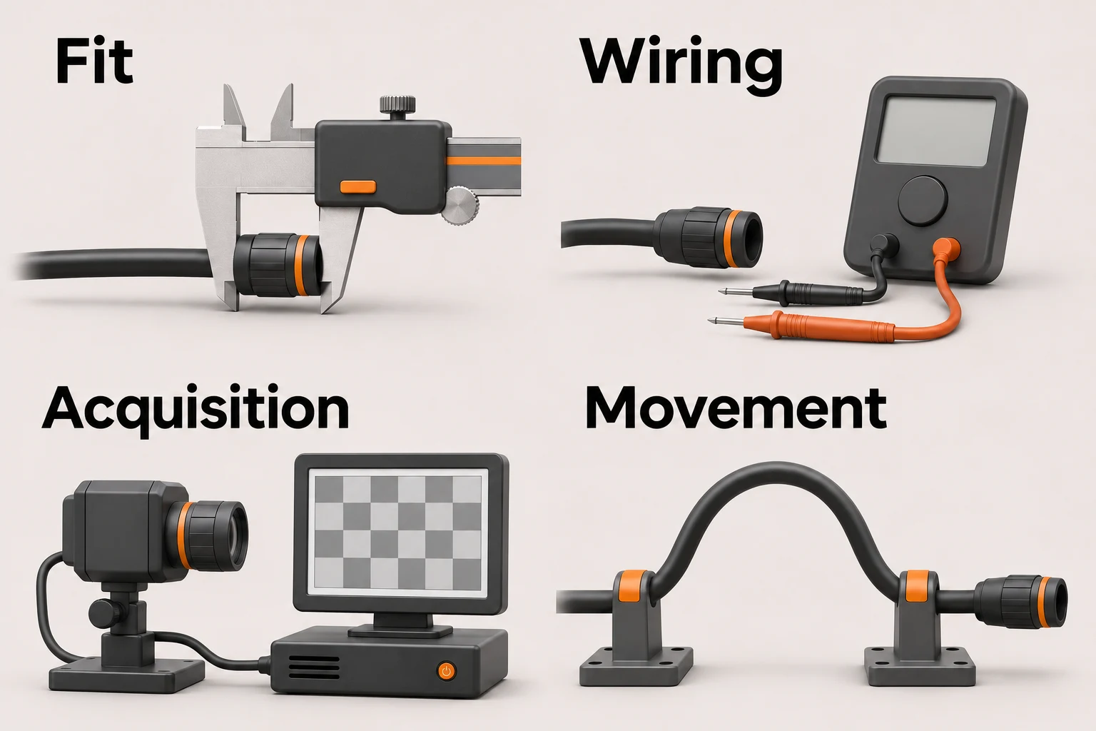
Mechanical fit
Compare plug engagement, screw access, cable exit, clamps and route with the approved drawing. Record its revision, dimensions and mating hardware.
Cable wiring
Check the approved netlist, including specified shield and unused conductors. Record sample ID, revision, method and electrical criteria.
Image acquisition
Record camera and host models, interface and cable path, resolution, pixel format, frame rate, trigger mode, simultaneous camera load and run duration. Compare received, incomplete or lost images and diagnostics against agreed criteria.
Movement and environment
Define bend or twist duty, environment, monitoring during and after the test, and acceptance criteria. Attach sample ID, conditions and results to the decision.
Drawing and Revision Control
Tie the quotation, sample decision and changes to drawing and BOM revisions.
Connector and cable definition
Identify both ends, cable and termination; include port photos and available mating drawings.
Assembly drawing
Record length datums and tolerance, branches or clamps, cable exit, fastening and labels.
Sample and change record
Identify each sample against drawing and BOM revisions; record connector, cable or route changes before approval.
Order documents
Specify required drawings, BOM, sample decision and inspection records, their revisions and providers.
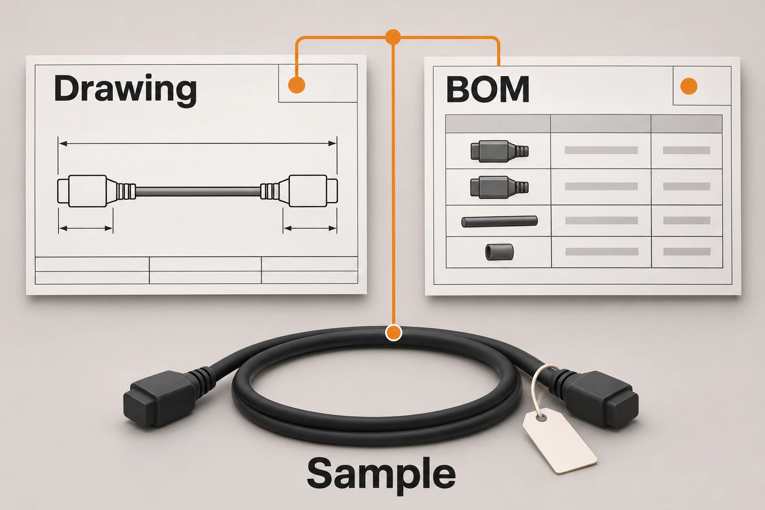
Include sample and planned order quantities with the drawing and BOM.
Send Camera Details and DrawingsContact Us
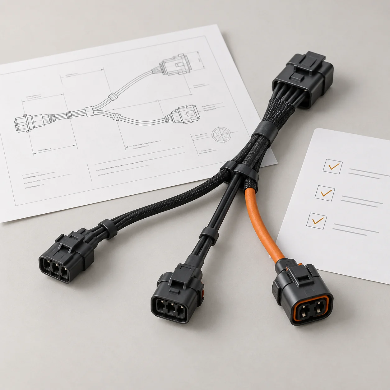
Tell JTY about your connector, wire harness or cable assembly project. Share the drawings, specifications or sample details you have for an initial review.
 Your Project