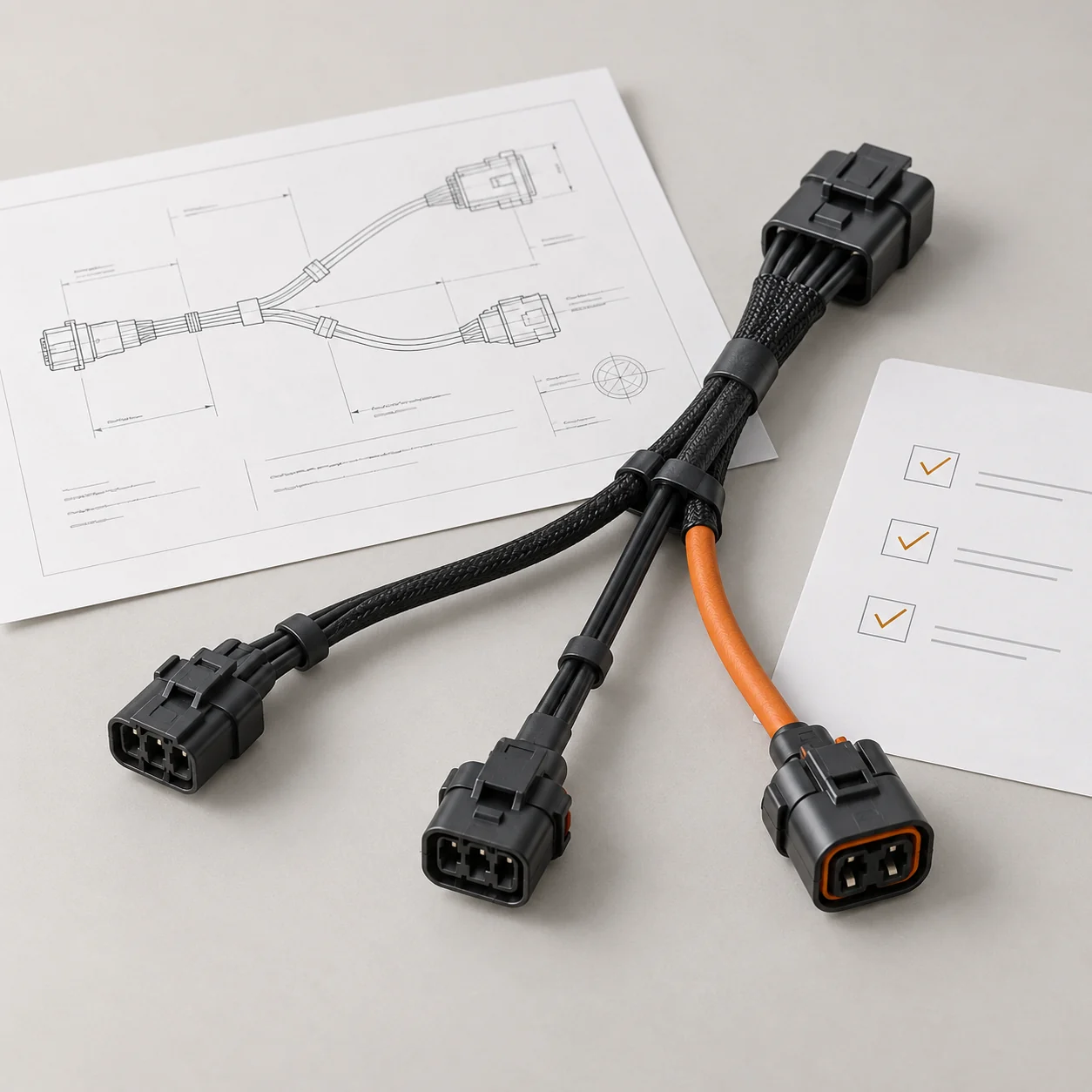
Commercial Terminals · Application Example
Internal Wiring Kit for a Payment Terminal
A terminal can use several similar-looking leads inside one enclosure. This example shows how to specify the connections and pack the right cables together for each terminal.
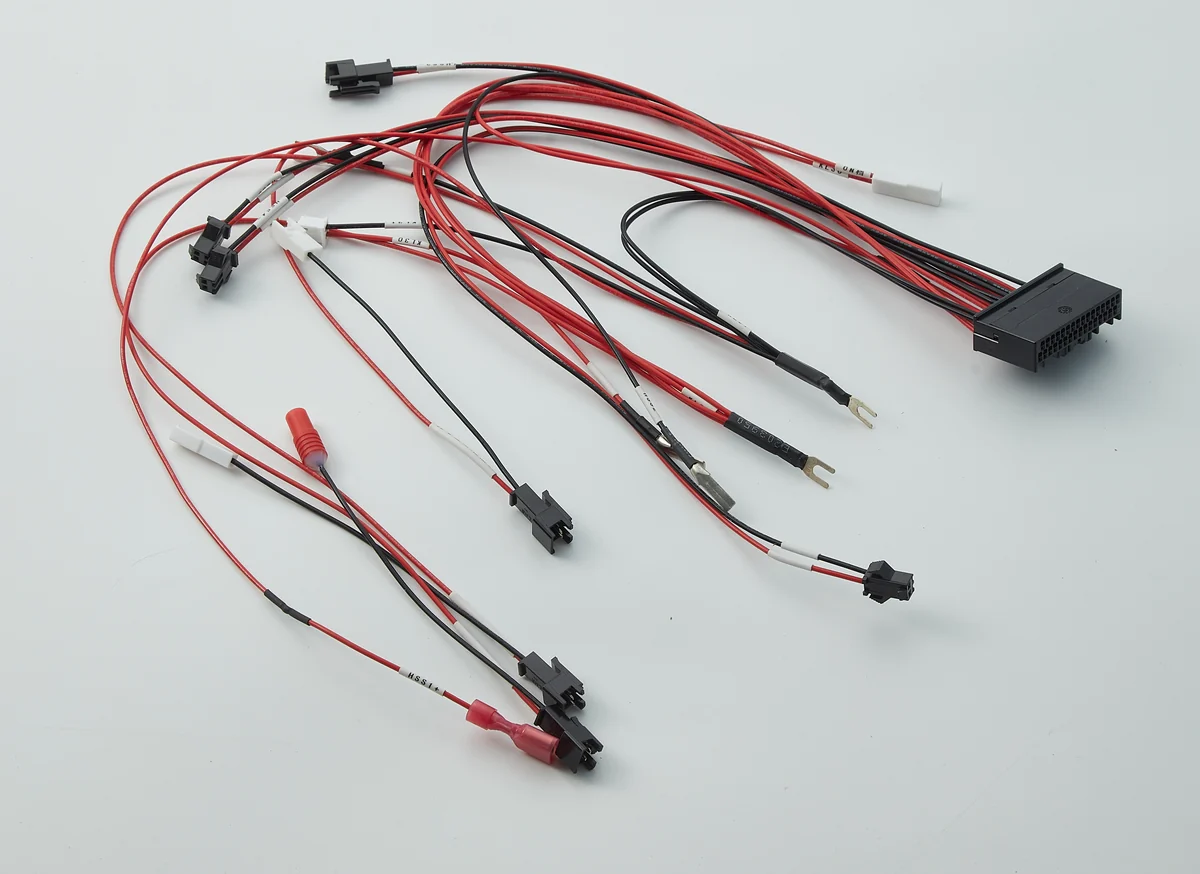
- Power, display and signal wiring
- Connector and pinout checks
- Kit contents by terminal revision
- One packing list per kit
Match the BOM to the Boards
Review the terminal’s board connectors and enclosure layout before releasing the kit. A short connector description can leave the mating part, orientation or pin numbering unclear.

- 01
Identify the Ports at Both Ends
Use board and port references to show where each lead plugs in. Confirm the mating part number, pitch and latch orientation against the board or mating sample.
- 02
Show Pin 1 and the Viewing Side
Mark the connector face used for pin numbering. For the display flex, specify which side the exposed contacts face at each end.
- 03
Check the Route in the Enclosure
Confirm the cable length, exit direction and clearance around screws, clips and the cover. Check that the flex can be inserted and locked with the boards in place.
What Goes in the Kit
This example groups the internal wiring by destination. Give each assembly its own part number and drawing revision, and list its quantity in the terminal’s kit BOM.
| Assembly | Example connection | What to specify |
|---|---|---|
| Power lead | Power input board to main board | Wire size and length, polarity, mating parts and pin assignments. |
| Display FPC | Display module to main board | Contact count and pitch, length, contact side at each end and any stiffener details required by the connector. |
| Multi-pin signal harness | Keypad module to main board | Latching housings, connector orientation and the point-to-point pin map. |
Check the Wiring and the Packed Set
Fit a sample set in the terminal first. Release the kit against the approved connection drawings and packing list.
- Physical fit
- Check connector seating and cover clearance. Verify the flex contact orientation and that the connector latch closes with the flex fully inserted.
- Electrical mapping
- Check continuity and polarity against the approved pin map. Define the points to test and which circuits must stay isolated.
- Kit completeness
- Match each bag’s part number, revision and quantity to the packing list. Confirm that similar assemblies for different terminal revisions are kept apart.

Send Your Drawing for a Quote
Attach a drawing, BOM, specification sheet or sample photos, and describe the application. JTY replies with questions or a quotation.