Industrial Robotics · Application Example
Wire Harnesses for Robot Assemblies
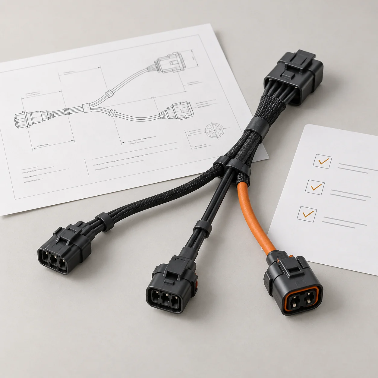
A harness that fits a robot at rest can pull at a connector when an axis moves. This example follows the route from the controller to the tool and shows what to define at each section.
- Fixed runs and moving sections
- Bend and twist conditions
- Clamp points and cable exits
- Sample fit and motion checks
Map the Route Before Selecting the Cable
Start with the installed connectors, the clamp positions and the axis travel. Mark where the cable stays fixed, bends repeatedly or twists.
- 01
Define Both Ends
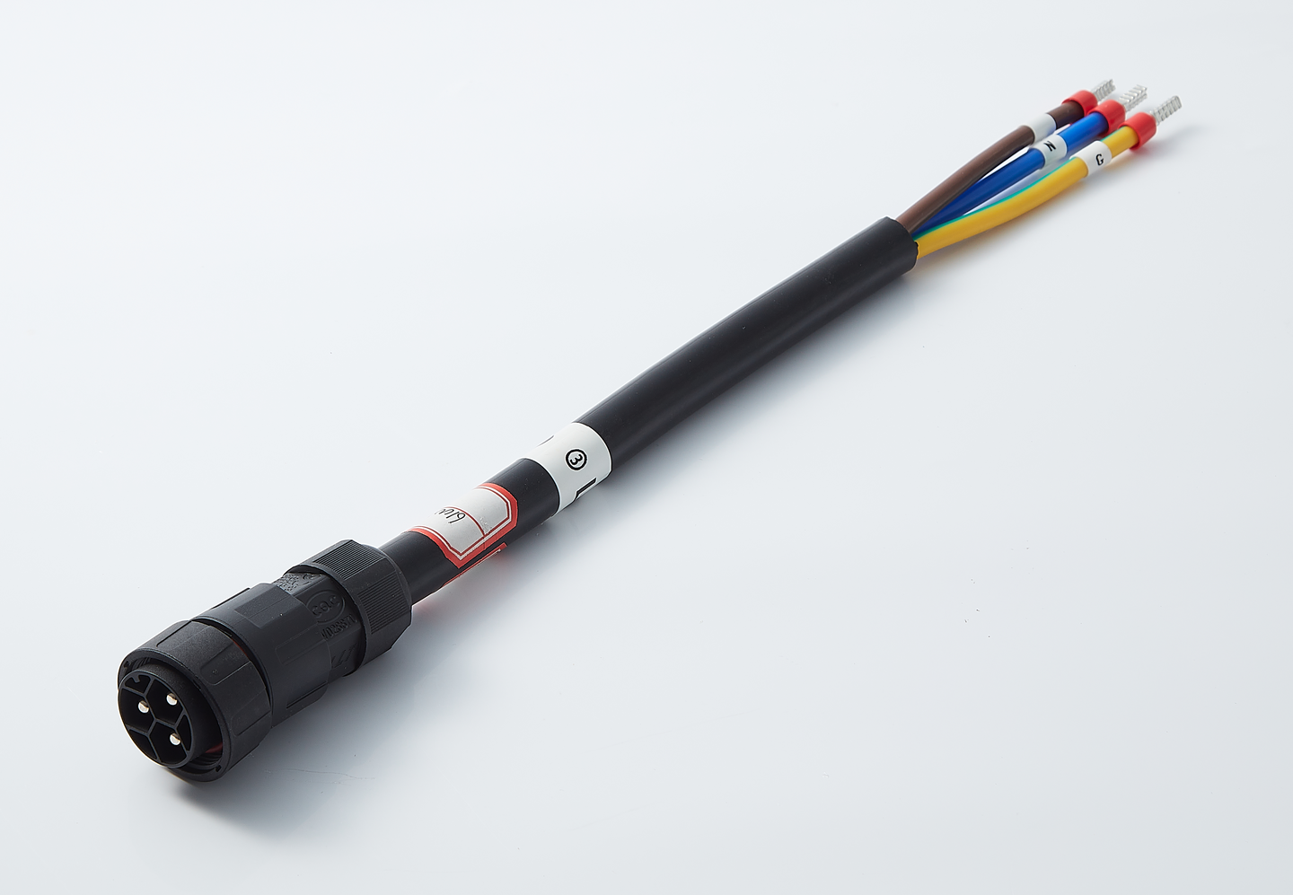
Provide mating part numbers, pin assignments and connector orientation. Add the shield termination detail where the circuit requires one.
- 02
Mark the Fixed and Moving Sections
Locate the clamps and the free cable between them. Show each section that bends or twists and how far the joint moves.
- 03
Check the Space Around the Route
Show nearby covers and brackets. Allow room for the connector and cable exit at both ends of travel and for access during service.
Specify Each Section of the Route
In this example, the controller lead stays fixed, the arm cable bends at a joint, and the wrist lead may twist as the tool rotates.
| Route section | Motion in this example | What to put on the drawing |
|---|---|---|
| Controller to base | Fixed run | End-to-end length, connector orientation, clamp locations and access for disconnection. |
| Across the arm joint | Repeated bending | Joint travel, minimum available bend radius, free cable length and fixing points. |
| Wrist to tool | Twist if the route follows wrist rotation | Twist angle, free length over which the cable can twist, exit direction and strain relief. |
Verify Fit, Wiring and Motion
Use the approved drawing revision for fit and electrical checks. If the order calls for a motion test, agree the fixture, movement and acceptance limits before building the sample.
- Fit and clearance
- Check mating, the cable exits and slack throughout the required axis travel. Look for pulling, pinching and rubbing around clamps, covers and brackets.
- Electrical checks
- Check continuity against the pinout. Where shielding is specified, verify its termination at the designated end or ends.
- Bend or torsion validation
- For repeated bending, agree the radius, stroke and cycle count. For torsion, specify the angle over the free length and the cycle count. Define when to check continuity and what counts as a failure.

Send Your Drawing for a Quote
Attach a drawing, BOM, specification sheet or sample photos, and describe the application. JTY replies with questions or a quotation.