Data Center Power · Application Example
Branched Cable Assemblies for Rack Power
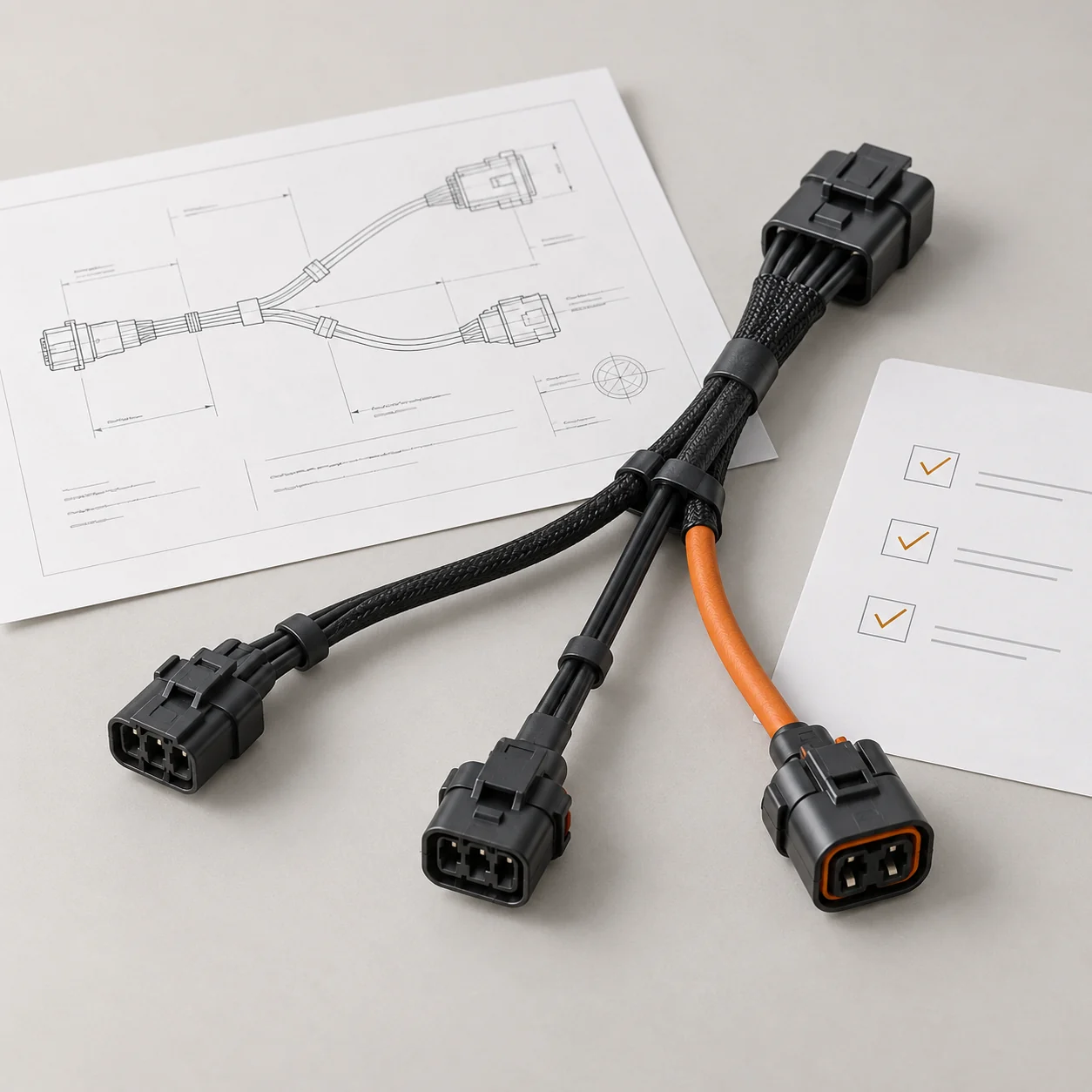
A rack harness can have the right overall length and still miss an equipment port. This example shows how to specify where each branch leaves the main run, what it connects to and how far it must reach.
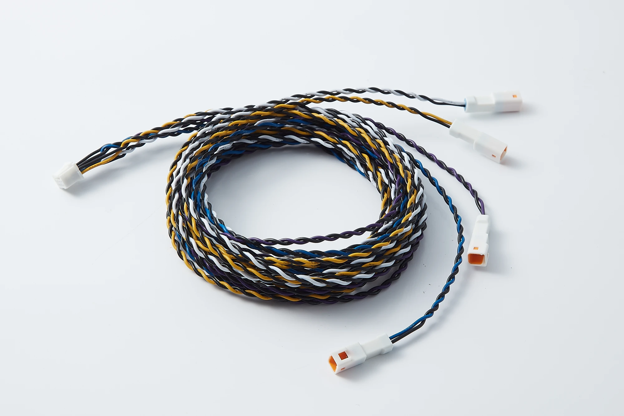
- Main and branch interfaces
- Breakout positions
- Free branch lengths
- Pin-to-pin connections
Start with the Rack Layout
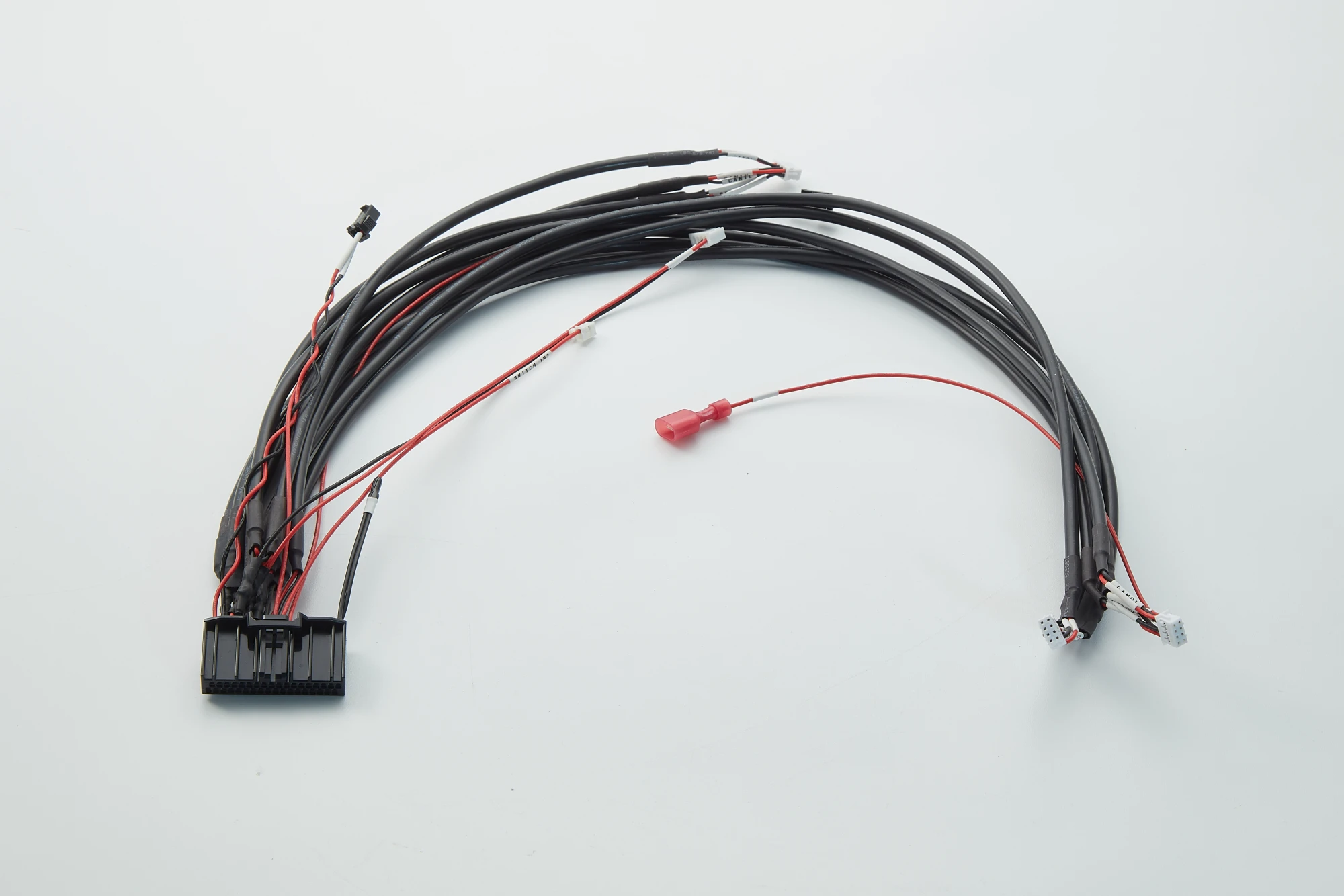
For an equipment bay with several connection points, map the installed route before setting branch lengths and end finishes.
- 01
Fix the Main Connection
Identify the mating connector, cable exit direction and point from which the drawing measures the main run.
- 02
Locate Each Branch Exit
Place each breakout along the rack route. Dimension the free length from that breakout to the corresponding connector datum.
- 03
Allow Room to Install and Service
Check the route around rails and brackets. Confirm cable access at each port and any slack needed to disconnect or remove the equipment.
Define the Branches on the Drawing
Two harnesses can share the same overall length. Moving the breakout changes how much of that length remains available to reach each port.
| Drawing ID | Example destination | What to specify |
|---|---|---|
| J0 · Main | Rack supply interface | Mating connector, pinout and datum for the main run. |
| B1 · Branch | Controller input | Breakout reference, free length and branch-end pinout. |
| B2 · Branch | Fan tray input | Separate free length, branch-end orientation and covering end if required. |
Check the Sample Against the Drawing
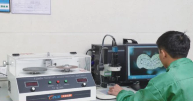
Fit the prototype in the rack to check branch reach, connector access and slack. Use the same drawing revision and agreed limits for the inspection record.
- Branch position and reach
- Measure the breakout and each free length from the drawing datum. Record the measurement path and whether the branch is straight or held in a fixture.
- Terminations and identification
- Verify the branch ID, connector orientation and end finish. If a crimp section is requested, specify the wire and terminal combination to sample.
- Electrical connections
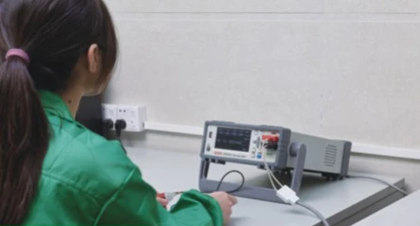
- Use the connection schedule to identify continuity points. If resistance is specified, record the endpoints, measurement conditions and limit.
Send Your Drawing for a Quote
Attach a drawing, BOM, specification sheet or sample photos, and describe the application. JTY replies with questions or a quotation.