Electric Vehicles · Application Example
800 V EV Battery Pack Harness
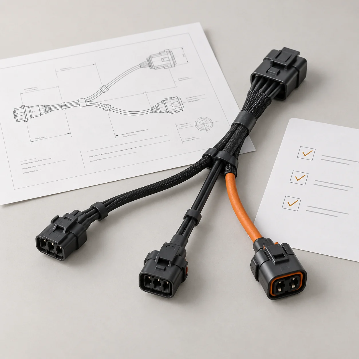
A replacement sensing harness for an 800 V battery pack must fit the existing enclosure and mate with the installed connectors. This example follows the drawing review, circuit definition and sample checks for that build.
- Pack connector and pinout
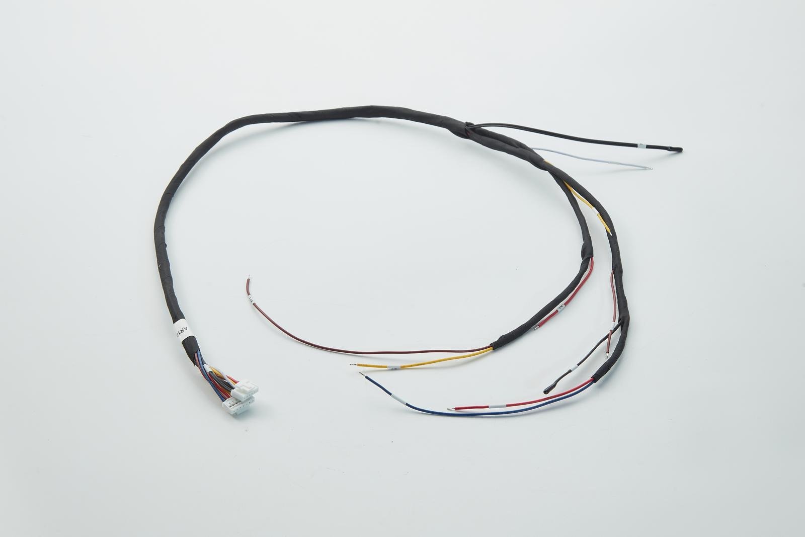
- Cell-voltage and temperature sensing
- Routing and mounting points
- Sample fit and validation checks
Define What Must Fit the Pack
Start with the released pack drawing and the mating parts. Identify which interfaces and mounting features must carry over and which routing details can change.
- 01
Keep the Pack Interface
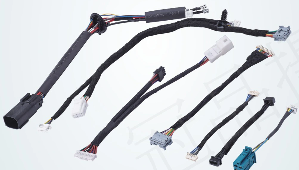
Confirm mating part numbers, keying, pin assignments and seal requirements. Mark connector exits and fixed mounting points.
- 02
Review Length and Weight Together
If weight is a priority, review branch routing and cable construction against circuit and installation requirements. Check reach and service clearance with a sample.
- 03
Agree on Validation
Identify the corrosion, vibration and electrical checks needed for the installation. Record the applicable conditions and approval documents.
Define the Circuits and Pack Interface
Use the pin map to separate sensing, communication and temperature circuits. Specify insulation and shielding for each circuit and its position in the 800 V pack.
| Circuit or interface | Example function | What to specify on the drawing |
|---|---|---|
| Cell taps | Cell-voltage sensing | Cell tap order, pinout and branch lengths. |
| BMS communications | CAN bus connection | CAN-H and CAN-L assignments, pair construction and any required shield termination. |
| Temperature sensing | Temperature sensor leads | Sensor part number, installed positions and lead lengths. |
| Main interface | Connection to the pack or BMS | Mating housing, cavities, keying, seal and cable exit direction. |
Validation & Production Checks
Base the validation plan on the installed environment and circuit requirements. List the method, sample quantity, acceptance criteria and records for each check.
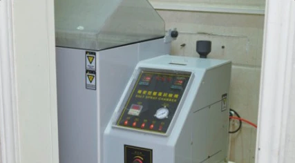
- Corrosion
- For a specified salt-spray test, identify exposed parts, sample preparation and what to inspect after exposure.
- Mechanical loads
- For vibration or shock checks, define how the harness is mounted and which connections to inspect afterward.
- Electrical checks
- Verify continuity against the pin map. If dielectric withstand is required, agree which circuits to test and set the conditions and limits.
- Production release
- Record the accepted drawing revision, required production checks and the inspection records that must accompany each lot.

What to Confirm Before Release
Review the installed sample, electrical checks and build records together.
- FitConnector access, branch reach and mounting points
- WiringPin assignments and agreed electrical checks
- RecordsAccepted drawing, BOM and sample inspection record
Send Your Drawing for a Quote
Attach a drawing, BOM, specification sheet or sample photos, and describe the application. JTY replies with questions or a quotation.