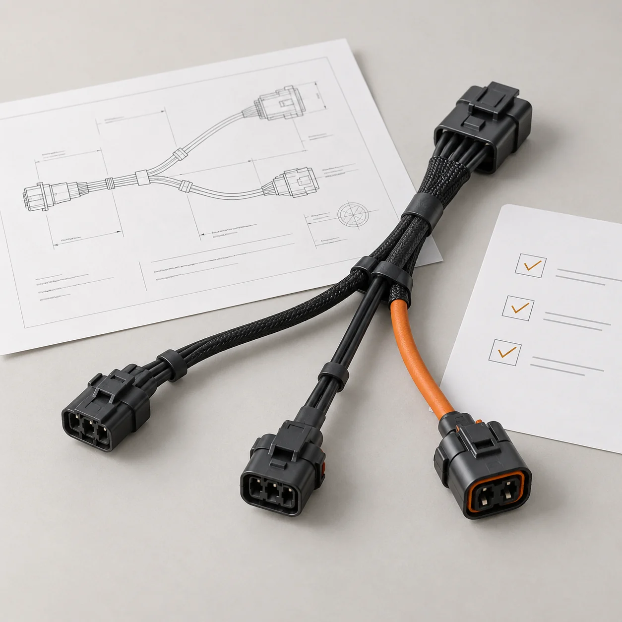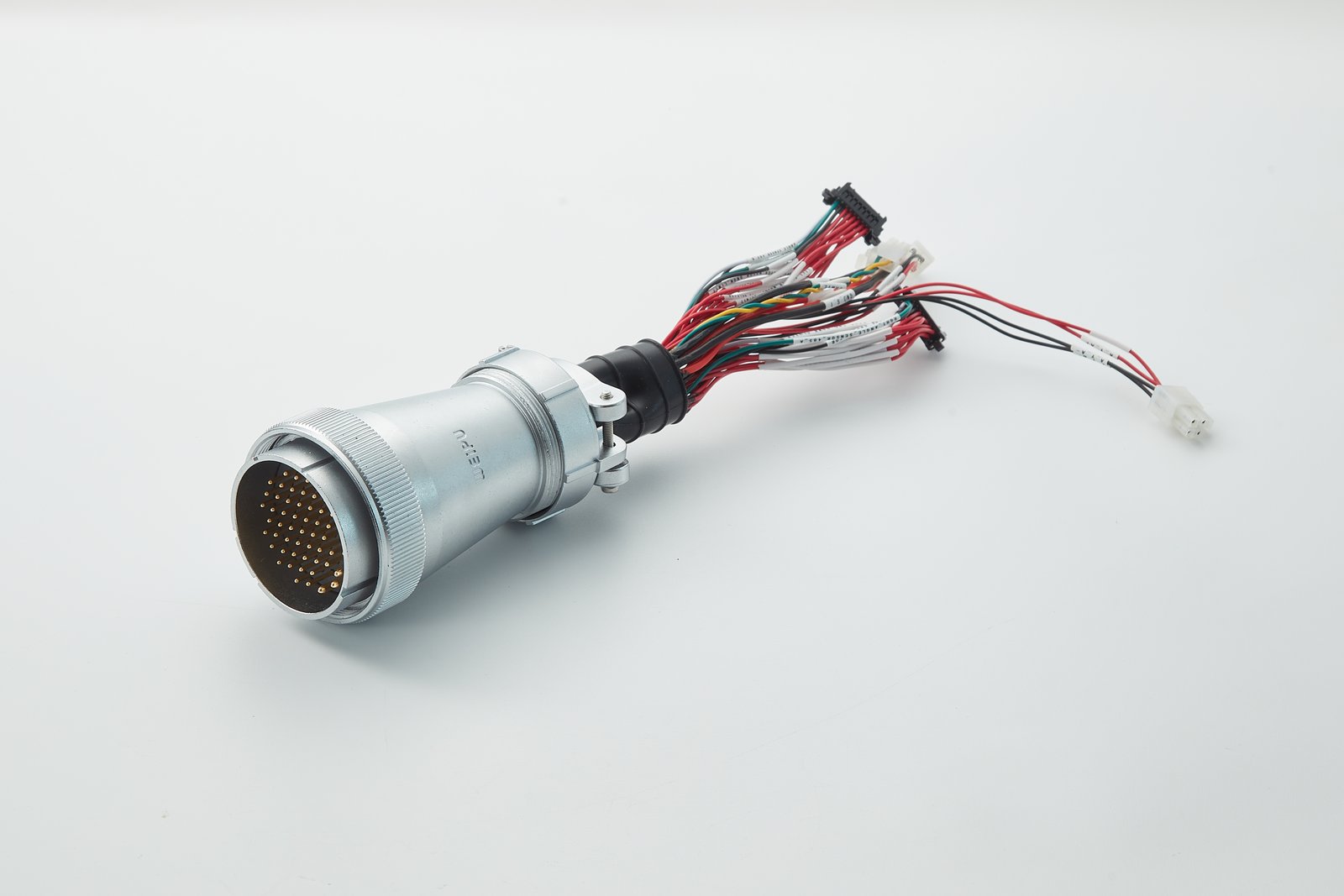
Circular connector assembly with labeled branch leads.
Payload Cable Assemblies
Circular Connector Assembly
Metal circular multi-pin connector wired to branch leads with printed identification sleeves.
Circular multi-pin · Branch leads · Printed sleeves
View Assembly Photo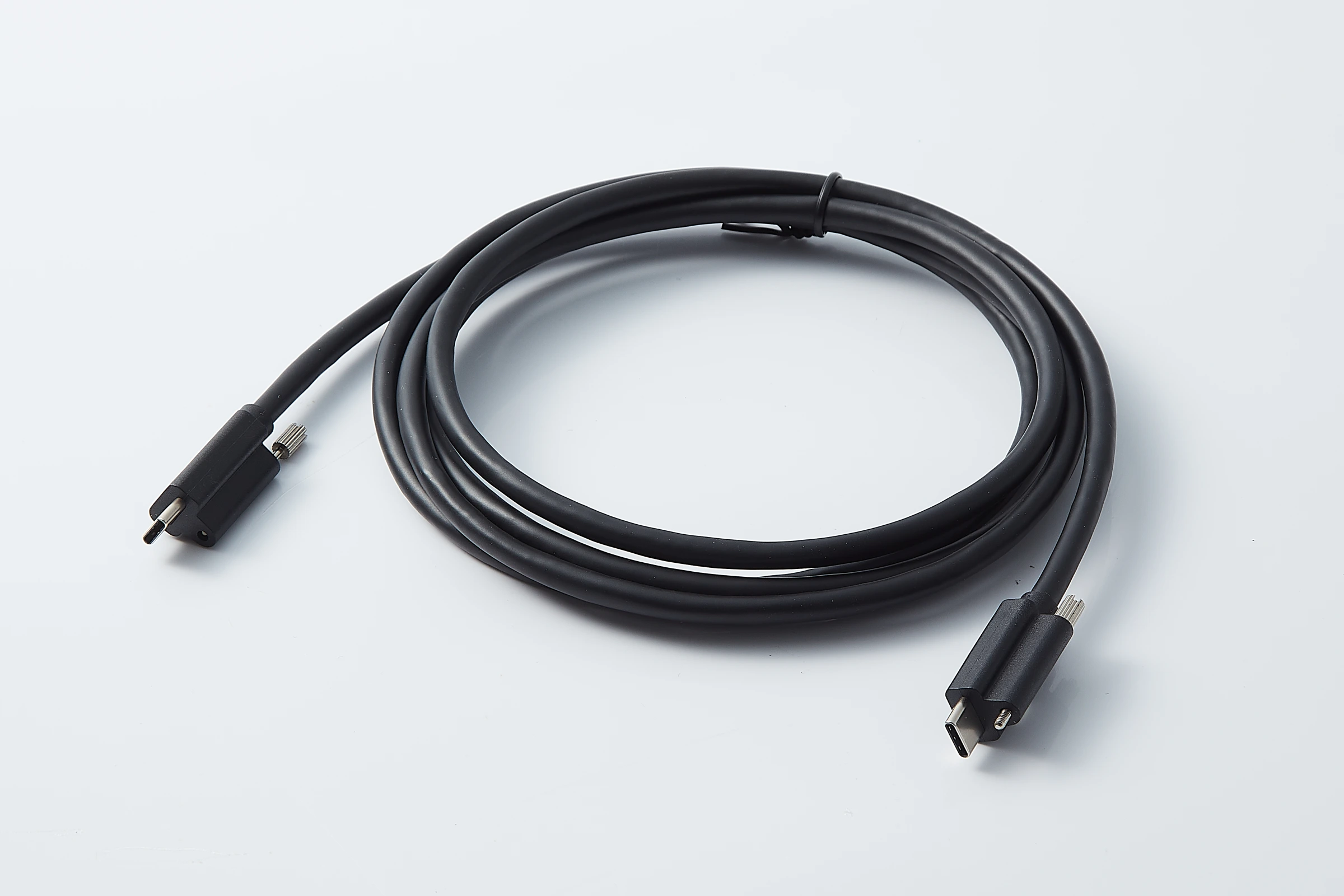
Screw-Lock USB-C Cable
USB-C to USB-C cable with locking screws at both plugs.
USB Type-C · Screw lock at both ends · Black jacket
View Assembly Photo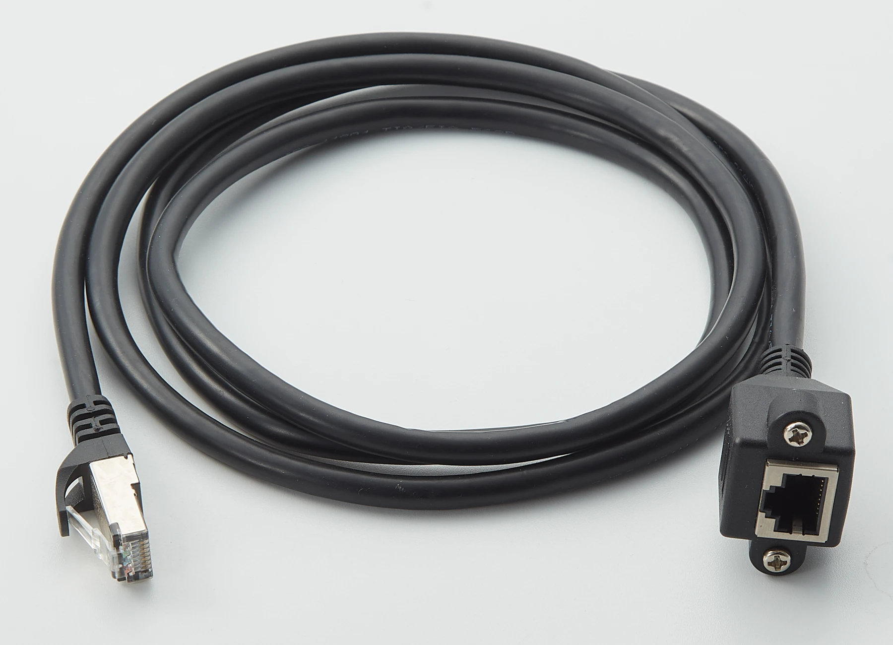
Panel-Mount RJ45 Ethernet Cable
RJ45 plug wired to a panel-mount RJ45 jack with a fixing flange.
RJ45 plug · Panel-mount jack · Fixing flange
View Assembly PhotoChoosing Payload Cables by Signal
Camera Links and Locking USB-C Plugs
HD cameras use HDMI, USB 3 or digital coax video links. HD cameras run on stable 12–24 V power rails. The USB-IF Type-C Locking Connector Specification defines single-screw and dual-screw locking plugs. The dual-screw plug suits applications where height is restricted. The dual-screw plug uses standard M2 screws. The single-screw plug is defined for applications with restricted width. JTY builds screw-lock USB-C cables.
LiDAR Data and Power Cables
LiDAR units often output Gigabit Ethernet or optical fiber data. Openelab lists a third-party Livox LiDAR cable that splits one M12 12-pin aviation connector into DC power, RJ45 Ethernet and a line for GPS or other synchronization. JTY builds RJ45 Ethernet cables, including panel-mount jack extensions.
RF Coax and Fiber
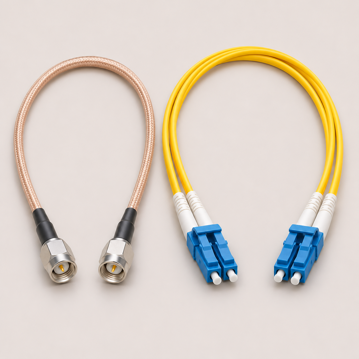
Long-range telemetry and RF data links use impedance-controlled coax or fiber. Fiber jumpers with ST or LC connectors carry gigabit data inside the airframe. Custom coax assemblies include RG-316 and RG-178, for example. JTY builds coaxial cable assemblies and fiber jumpers.
Modular Connectors and Supply
A camera and gimbal block can plug into the main harness through one multi-pin connector. Modular harness sections with quick-disconnect interfaces let sensors be replaced in the field without a complete rewire. JTY sources wire and connectors. JTY also assembles connectors that you supply.
Tests for Payload Cables
Continuity and Resistance
JTY can check continuity, polarity and pin assignment on finished cables against the pin-to-pin table on your drawing. JTY measures circuit resistance with a precision tester.
Dimensions
JTY's 2D optical measuring instrument measures terminal, crimp and molded-end dimensions.
Withstand Voltage
JTY's withstand-voltage tester checks insulation between circuits at the test voltage on your drawing.
Connector Mating Force and Cycles
JTY's insertion and withdrawal tester checks the mating force and cycle count of payload connectors.
Gimbal Cable Bending
Gimbals and other moving parts use continuous flex-rated cable. Minimum bend radii for these cables are often at least 10 times the cable diameter. As an example, a 6 mm cable at 10 times its diameter needs a bend radius of 60 mm or more. JTY's wire bending tester checks the flex life of moving sections such as gimbal cables.
Payload Connection Points
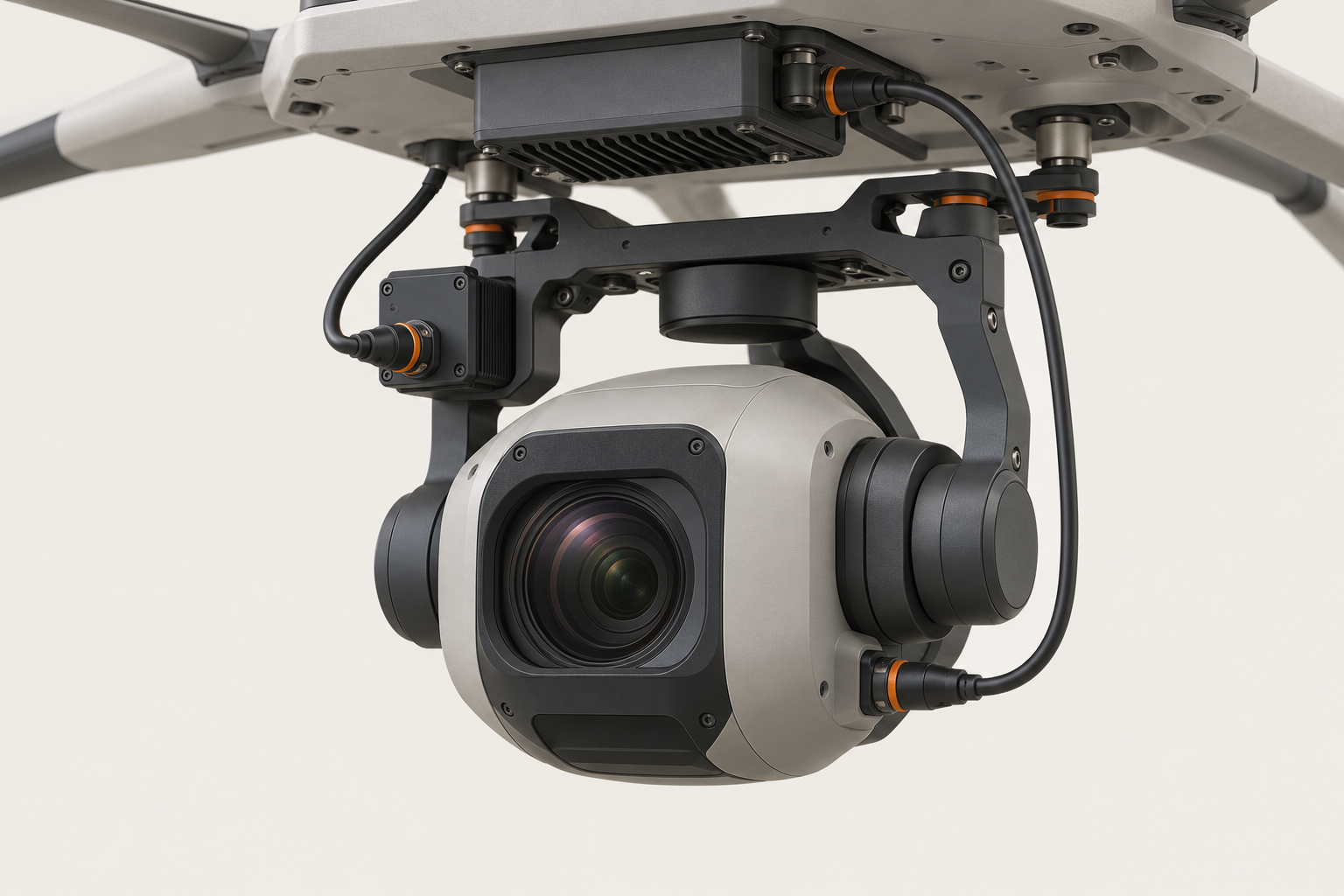


Camera & Gimbal Payloads
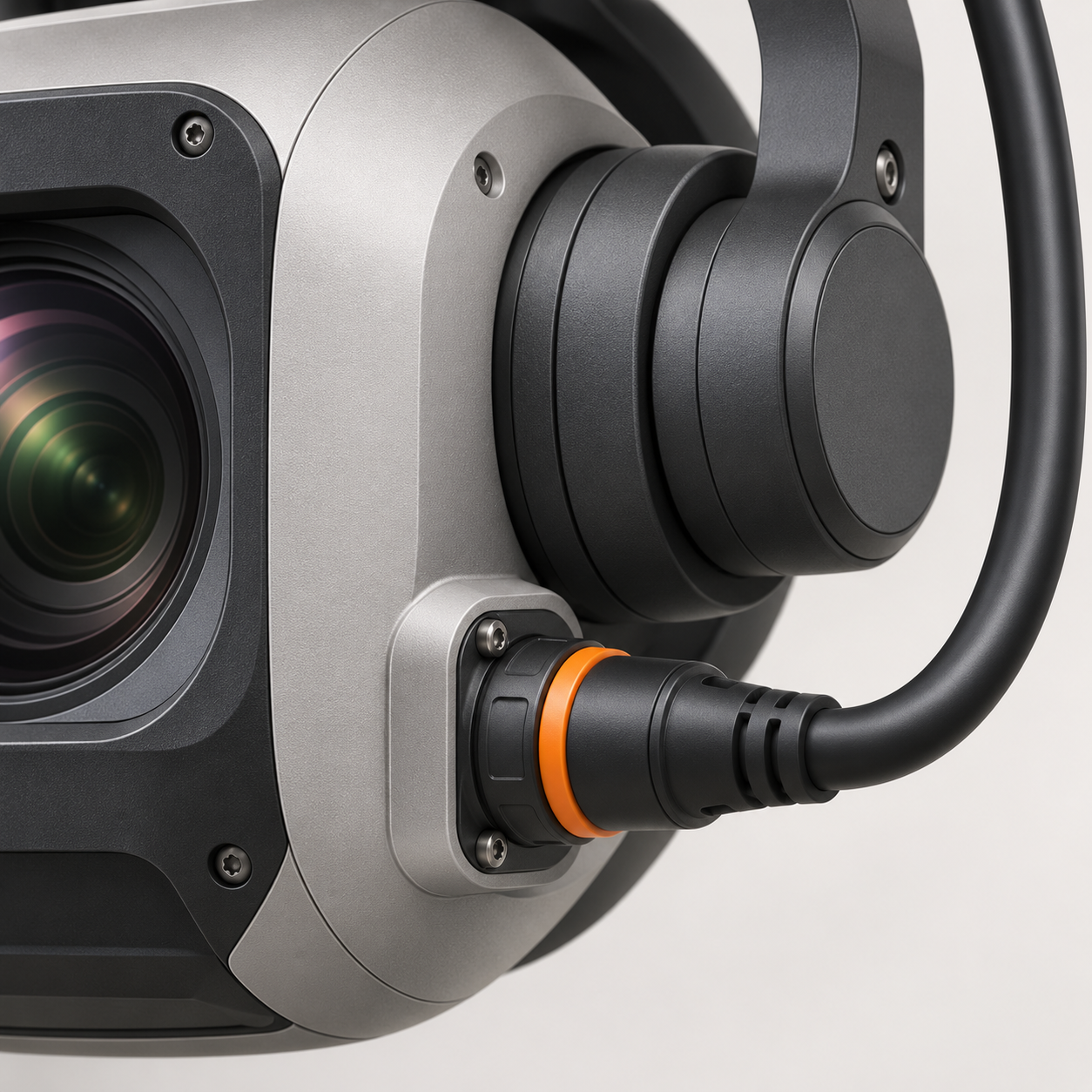

Custom Payload Cable Configurations
Finished cable lengths and branch positions made to the customer drawing.
Connector orientation defined by the assembly drawing.
Connections defined by the project pin-to-pin table.
Braided cable covering and printed lead labels.
UAV Payload Assembly Specification
| Specification | JTY Verified Capability / Reference | What to Specify on Your Drawing |
|---|---|---|
| Weight & conductors | Compact payload harnesses can be built to the specified wire schedule, ends and finished-weight target. | List wire size by circuit, jacket material, target weight and temperature. |
| Electrical interfaces | Agree on continuity, polarity and any resistance limits against the payload and power circuit map. | Give working voltage, peak/continuous current, shield termination and pinout. |
| Retention & routing | Give the connector retention requirements and the available movement and service-loop space, including fixed points. | Mark retention points, gimbal/payload travel and end protection. |
| Sample & batch validation | Samples ship 3 to 7 days after drawing confirmation. Agree on the acceptance criteria before release for batch production. | Specify vibration/flex checks and resistance limits for sample approval. |
Ordering FAQ
How do I share the payload connection details?
Provide connector and mating references, contact numbering views, power and signal assignments and the payload-side mounting layout.
What should I specify for a movable payload?
State the travel, available clearance, service loop and fixing points. Give a bend or twist profile and the required sample checks.
How do I control harness weight?
Specify a finished weight target, maximum branch lengths and any cable type or shielding that the payload requires.
Contact Us
Tell JTY about your connector, wire harness or cable assembly project. Share the drawings, specifications or sample details you have for an initial review.