Drone & UAV Wire Harness Manufacturer
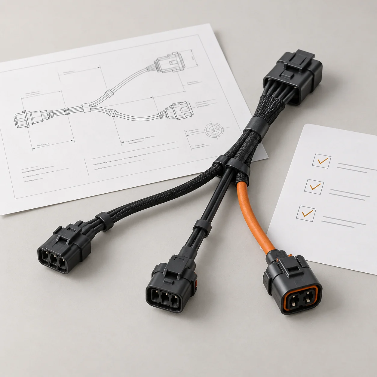
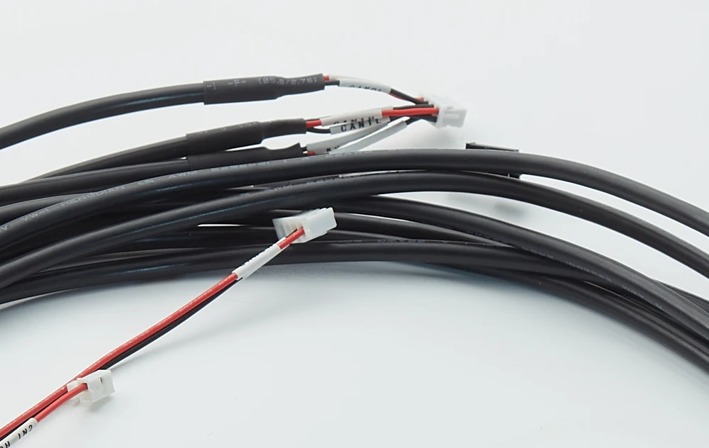
JTY manufactures drone and UAV wire harnesses for industrial, agricultural and payload systems, including power leads, branched harnesses and connector-to-connector cable assemblies. JTY builds the leads in silicone or PVC wire. Ends exposed to rain in flight use IP67 waterproof harnesses with circular or flange connectors. Samples are ready in 3–7 days once the configuration is agreed. You check fit, routing and flight behavior on the sample before batch production.
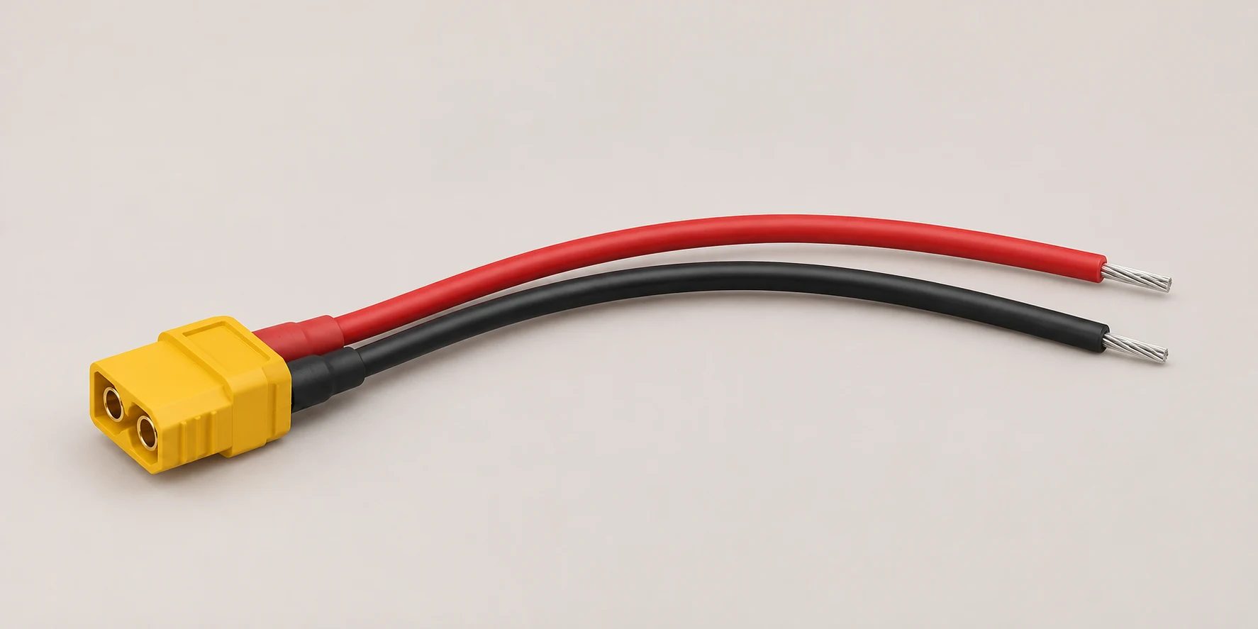
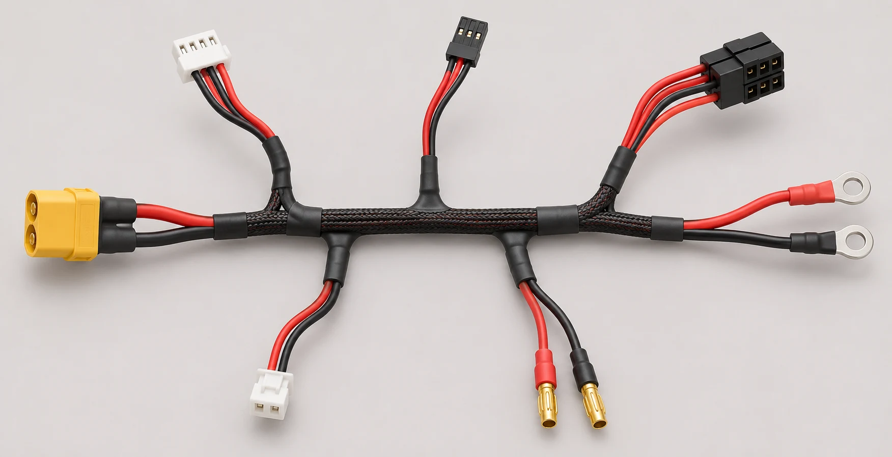
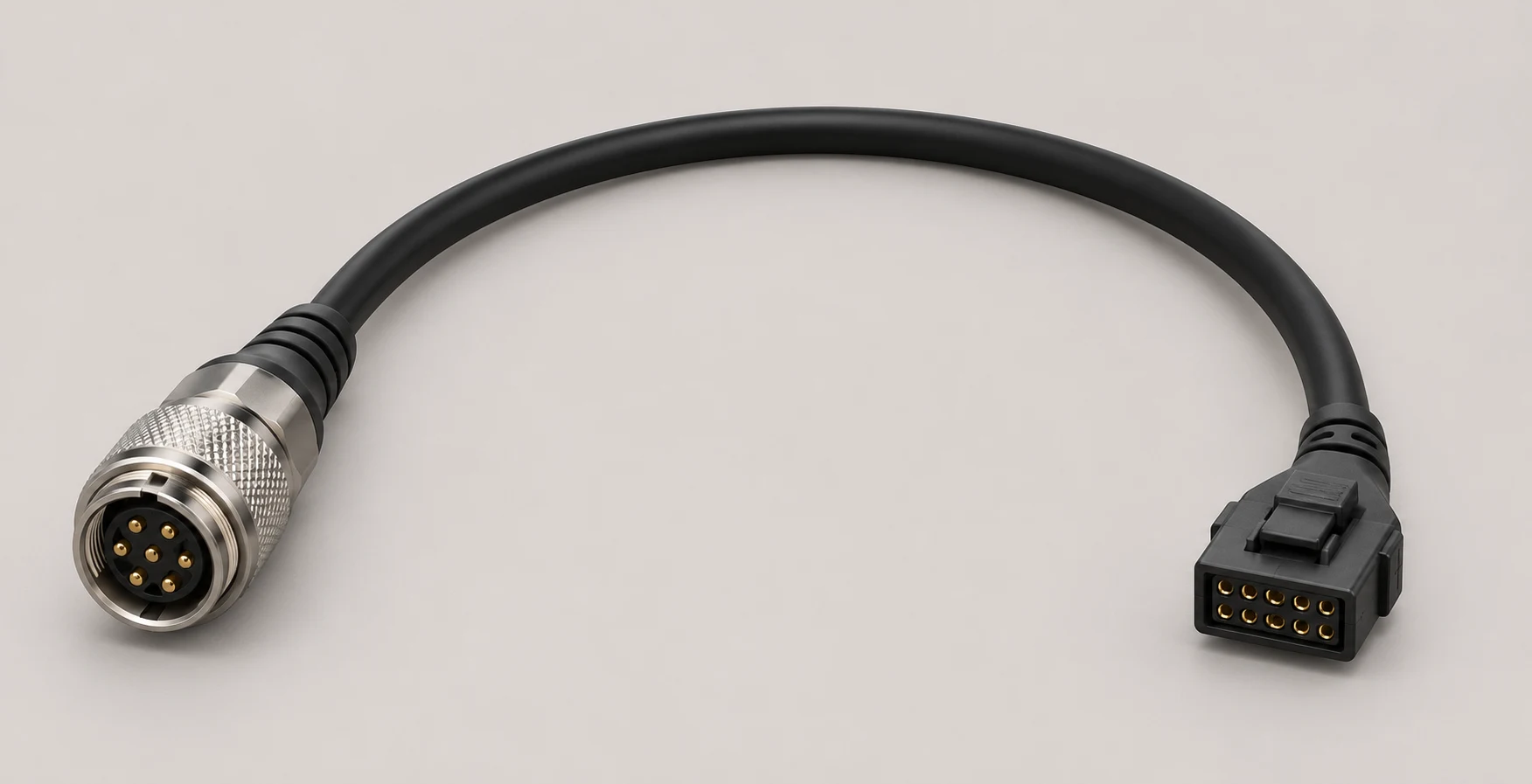
Drone and UAV Harness Categories
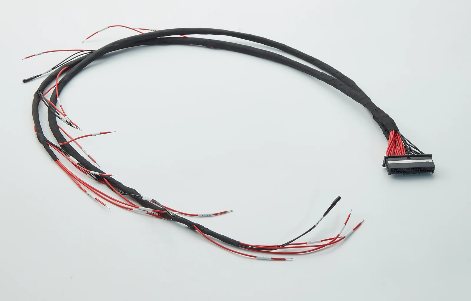
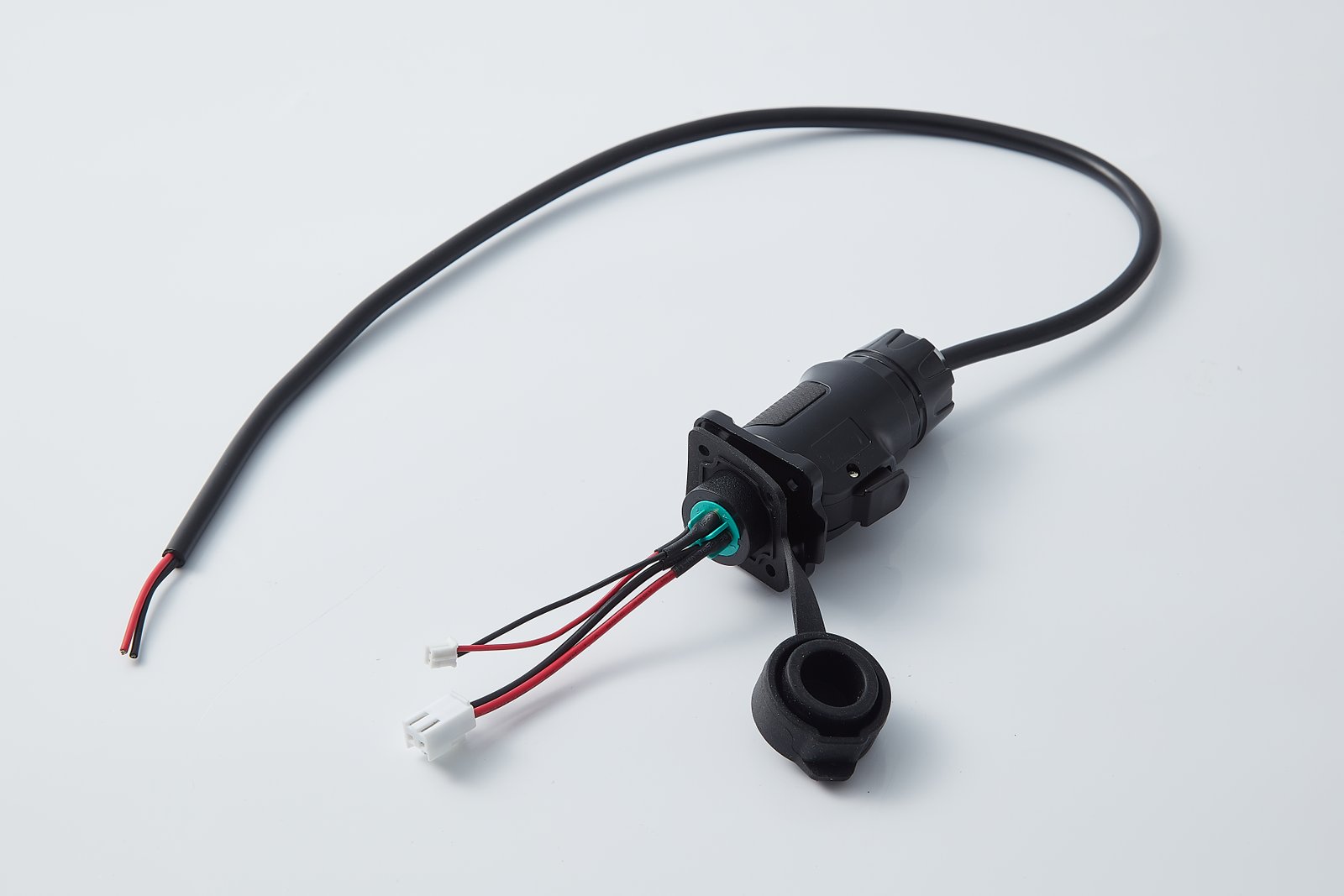

Industrial Drone Wire Harnesses
Interface cables and branched harnesses for inspection and mapping UAVs.
Braided sleeve · Printed lead sleeves
View Industrial HarnessesWire and Connectors by Drone Circuit
TeleWire’s UAV harness guide gives a typical wire size and connector for each circuit below.
| Circuit | Typical wire | Typical connectors | Main concern |
|---|---|---|---|
| Battery to power distribution | 10–12 AWG silicone | XT60, XT90 | Pulse current, low resistance |
| ESC to motor | 14–18 AWG silicone | 3.5 mm bullet, soldered | Vibration and current |
| Flight controller signal | 26–30 AWG | JST-GH 1.25 mm, Molex PicoBlade | Weight, keyed mating |
| GPS, compass and sensors | 28–30 AWG, twisted or shielded | JST-GH, Hirose DF13 | Noise from ESC and motor wiring |
Current, run length and the allowed temperature rise decide the final size of each lead. JTY can load a sample at your current and measure its temperature rise before the wire size is fixed.
The PX4 autopilot cabling guide recommends routing power and signal wiring apart. It also recommends twisting I2C and CAN pairs. In the table above, TeleWire flags the GPS, compass and sensor runs for noise. Those runs are the first to mark for twisting or separation.
Terminations and Protection
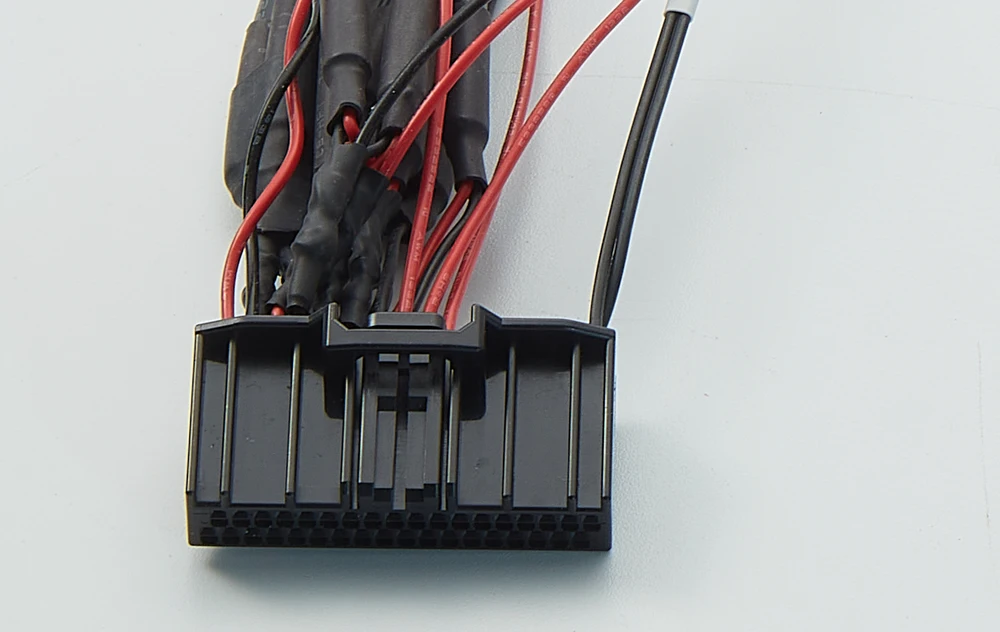
Crimped Terminations
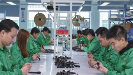
Motor and propeller vibration concentrates stress at the wire terminations, according to TeleWire’s guide. The guide calls for strain relief, potting or service loops at these joints in place of unsupported solder joints. JTY’s plant runs automatic terminal machines for crimping. First samples come with a crimp cross-section report. The report shows the conductor compression for each terminal type on the sample. You review it before approving batch production.
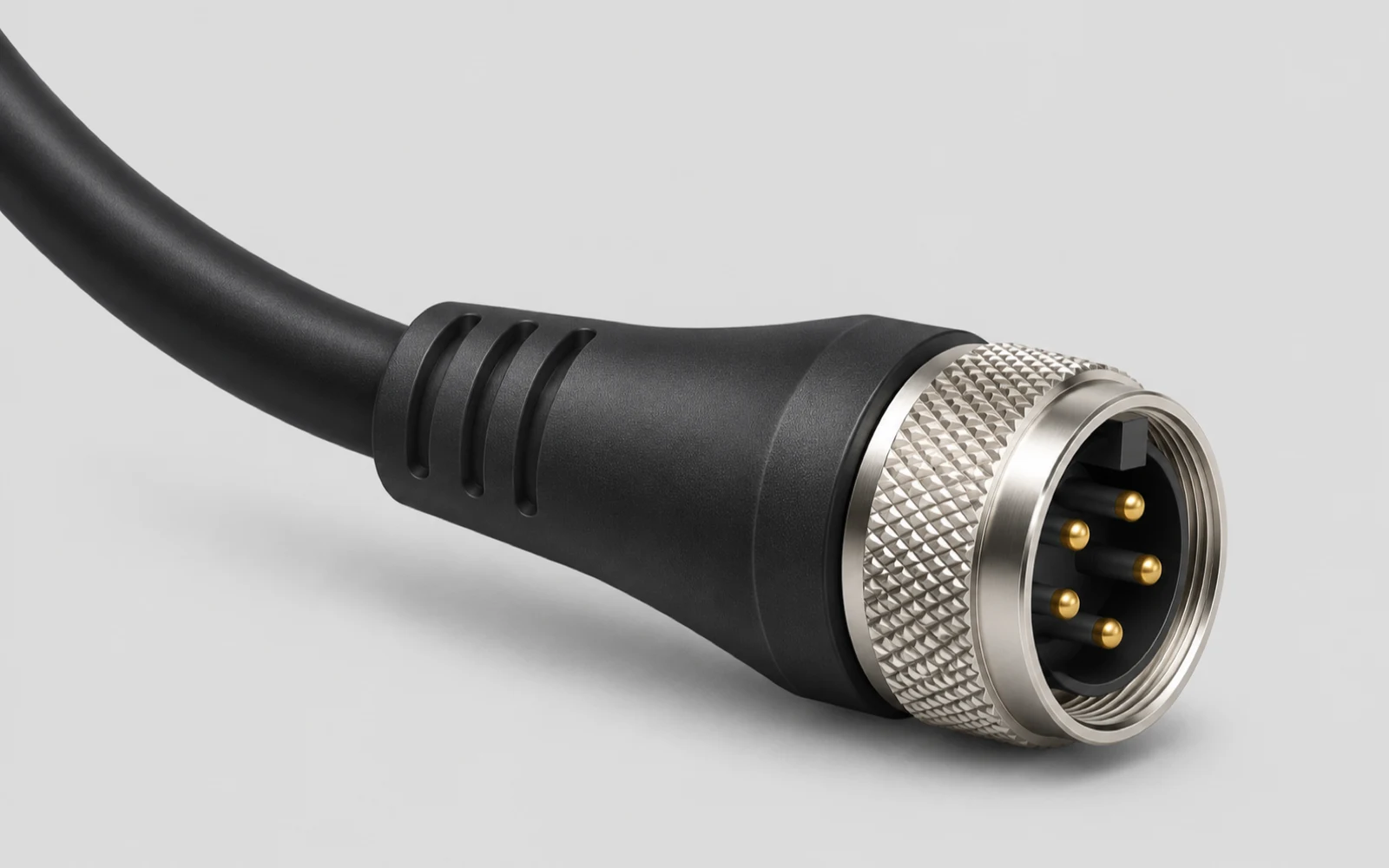
Built and Tested in JTY’s Plant
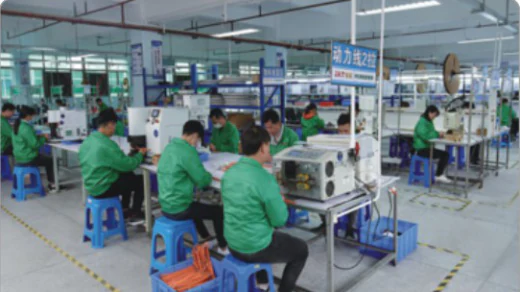 Harness assembly
- 2,000 m²
- Facility
- 10
- Assembly lines
- 30+
- Vertical injection molding machines plus other machines such as automatic terminal machines
Manufacturing checks
- Crimp cross-section
- What it checks on a drone harnessConductor compression in a sectioned crimp
- Checked againstThe terminal maker’s crimp specification
- 2D optical measurement
- What it checks on a drone harnessTerminal, crimp and molded-end dimensions
- Checked againstThe tolerances on your drawing
- RoHS spectrometer
- What it checks on a drone harnessRestricted substances in wire and connector materials
- Checked againstThe RoHS limits
Testing & Inspection
Power leads need resistance and temperature-rise checks. Moving cables such as gimbal leads need bending cycles. Ends exposed to humidity need temperature-humidity tests. Terminals exposed to salt air or corrosive spray need salt spray tests.
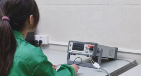 Resistance measurement
| Test | What it checks on a drone harness | Checked against |
|---|---|---|
| Precision resistance | Resistance of power leads and contacts | The limit on your drawing |
| Withstand voltage | Insulation between circuits | The test voltage on your drawing |
| Electronic load | Heating of power leads at the current on your drawing | The temperature-rise limit on your drawing |
| Wire bending | Flex life of moving sections such as gimbal cables | The bend cycle count on your drawing |
| Insertion and withdrawal | Mating force and cycles of battery and payload connectors | The force and cycle count on your drawing |
| High/low temperature aging | Insulation and contacts after hot and cold exposure | The temperatures and hours on your drawing |
| Temperature-humidity | Insulation and contacts after damp heat | The temperature, humidity and hours on your drawing |
| Salt spray | Corrosion of terminals and connector shells | The salt spray hours on your drawing |
From Drawing to Batch Production
01 Drawing Review
The JTY engineers who review the drawing stay on the project through samples, batch production and repeat orders.
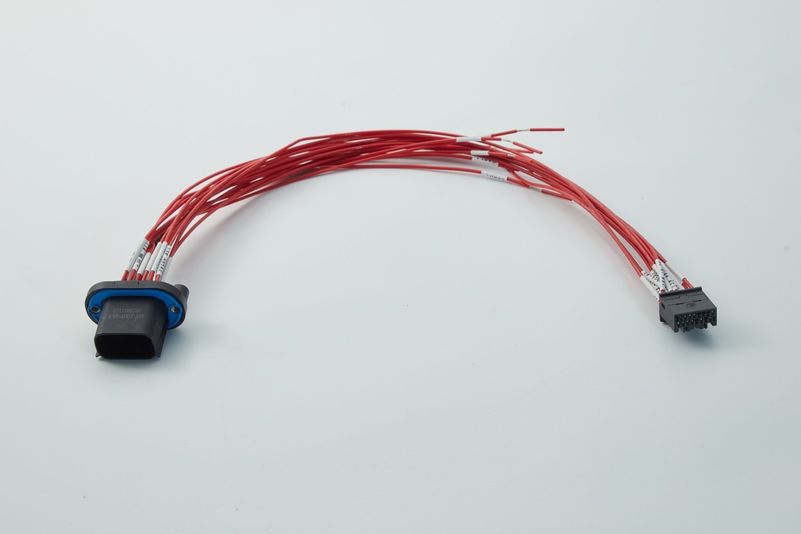

Designing for Installation and Service
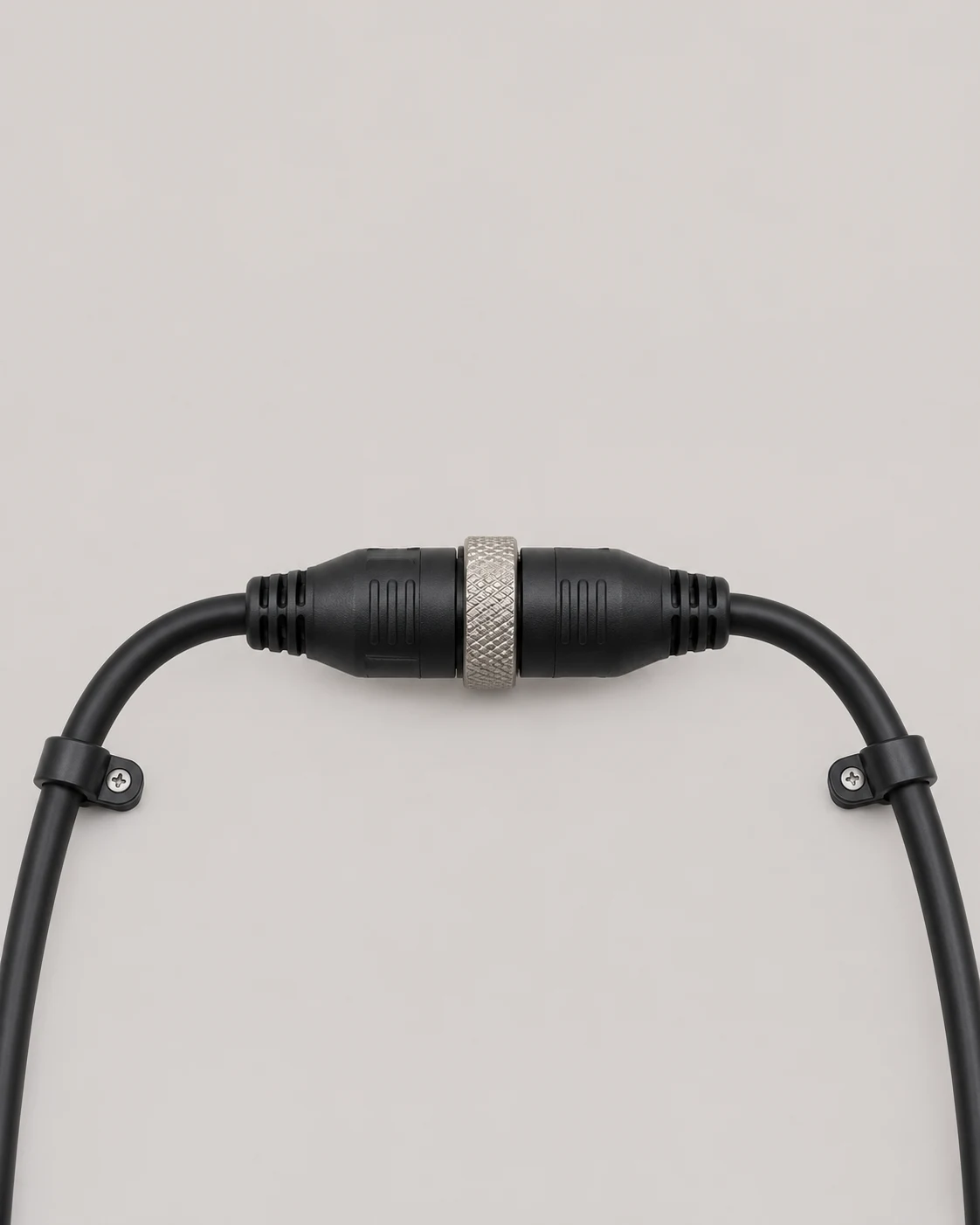
Replaceable sections
A continuous harness has no intermediate disconnect; a separable branch lets a removable arm or payload be disconnected at a defined interface. Decide which part will be replaced and mark that connection on the drawing.
Connector access
A connector only helps service if its release or coupling can be reached and the mating halves can be separated with surrounding parts installed. Check the access and removal path on the sample before fixing the connector position.
Routing at the interface
Mark where the harness is secured and where the branch must move during installation or removal. Check that the sample reaches the connection without being pulled tight or rubbing adjacent parts.
Contact Us
Tell JTY about your connector, wire harness or cable assembly project. Share the drawings, specifications or sample details you have for an initial review.