Connector-to-Connector Cable
Right-angle circular connector and modular plug on one continuous cable. It links an outdoor unit to a controller or network port.
Home / Products / Waterproof Wire Harness
IP67 harnesses for outdoor and wet equipment. JTY builds waterproof wire harnesses on sealed circular and flange connectors, with modular or rectangular plugs at the dry end. For component selection, see the waterproof battery connector guide for mating, panel and cable sealing conditions.
Each finished harness is checked for continuity and miswiring before it leaves JTY's plant.
Makers of electric two- and three-wheelers, balance vehicles, outdoor lighting, drones and smart appliances install the harness as delivered, with every connector and tail in place.
Right-angle circular connector and modular plug on one continuous cable. It links an outdoor unit to a controller or network port.
Circular connector at one end, with two open tails at the other. The tails are terminated inside the device housing.
Metal flange socket with a tethered cap, and three rear tails ending in two white housings and one black housing. It mounts through the device wall.
Black flange socket and cap, with one long open-ended cable and two short connector-ended leads.
Rectangular connector at one end, and a circular connector with separate red and black leads at the other.
| Application | Water exposure | Rating to ask for |
|---|---|---|
| Electric two- and three-wheelers, balance vehicles | Rain, road spray | IP67 at every exposed connector |
| Outdoor lighting | Rain, brief flooding at ground level | IP67 at the fixture connector |
| Landscape fountains | Splash above the waterline, continuous immersion below it | IP67 above the waterline. IP68, with depth and duration stated, for submerged fittings |
| Drones | Rain and spray in flight | IP67 at every exposed connector |
| Smart appliances | Splashes, condensation | IP67 at connectors near water |
Buyers who pressure-wash the equipment list it on the enquiry as a separate IPX9 requirement.
More than 30 vertical injection molding machines run in JTY's plant, alongside its automatic terminal machines.
Crimping and assembly. Terminals are crimped on automatic terminal machines. Housings and seals are fitted at assembly benches before each connector is closed. Buyers approve the first samples against a crimp cross-section report that ships with them.
Electrical checks. Continuity, miswiring, resistance and withstand voltage are tested at JTY's test stations.
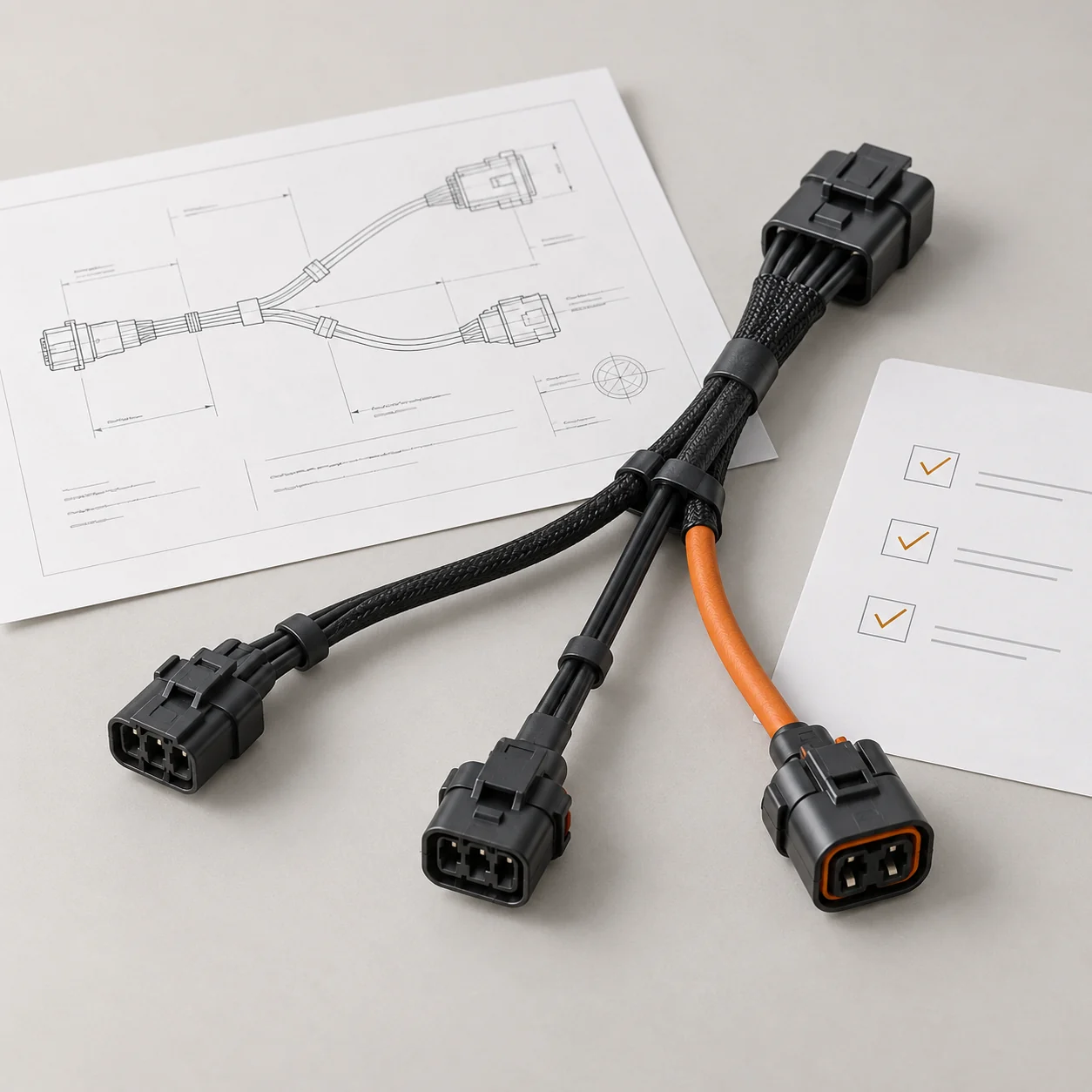
JTY measures the pin connections, wire lengths and parts on your sample and returns them as a drawing. Production follows the version you approve.
Salt-spray, temperature and humidity testing, and high and low temperature aging run in JTY's own test chambers. UV exposure belongs on the test request as a separate item.
Harnesses built on standard sealed connectors need no new mold. A custom molded end is made in JTY's own molding workshop.
This example has a straight modular plug and an angled circular connector on one continuous jacketed cable.
Straight modular end. The modular end has a straight cable exit. Specify its mating reference and wiring assignment; the visible plug shape does not identify a network protocol.
Angled circular end. The circular end turns across the cable route. Match its keying, mating reference and exit orientation before assigning the assembled connection a protection requirement.
Define the protection requirement. The product photograph does not establish an IP grade or network protocol. Protection and electrical requirements belong to the selected finished assembly.
Mating and cable route. Both mating references should be specified, keying and the required wiring map. Define cable length between agreed end datums and the circular connector exit direction so the assembly drawing describes the installed route.
Sealing and included parts. List the required connection state, cable entry and any cap or sealing accessory in the enquiry. The quotation and acceptance specification should state which supplied parts and assembled conditions the protection requirement covers.
A Rectangular connector end. Stays on the dry side inside the equipment and needs no seal of its own.
B Circular threaded connector. The threaded coupling secures the circular connector. Vibration resistance depends on the connector and locking arrangement.
C Panel flange. Seals to the device wall with a gasket under four screws.
D Tethered cap. Protection of an unmated socket depends on the specified rating with the matching cap fitted. The tether keeps the cap on the harness during maintenance.
Cable entry. The cable-entry seal is sized to the jacket of the cable on your drawing or sample. Changes to the cable need a sealing-fit review and may require a different entry part.
Finished length runs from the connector datum R to each wire tip T.
The jacket stop S sets the free wire left for termination, and stripped tails also carry a strip length.
Each rear tail has its own length from the flange datum P to its end housing. The three ends can sit at three different boards.
Quotes follow the R–T and P–T lengths on the drawing.
Name the device, where the harness meets water, each connector part number and the R–T or P–T lengths, or send a sample.
 Your Project